Output driver not working for P1.13 on nRF5340 DK

I am trying to set up two GPIOs to control an external chip. Development and testing is currently using the nRF5340 DK. NCS version is 2.5.0.

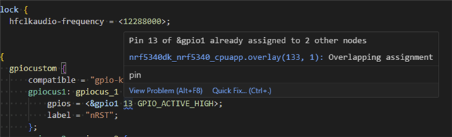
In my nrf5340dk_nrf5340_cpuapp.overfile, I have the following. There are other GPIOs, but ignore those for now. Also, ignore the fact that reset should be an open-drain. I am just sanity testing right now. The pins are not connected and only being monitored with a logic analyzer.

/ {
    gpiocustom {
        compatible = "gpio-keys";
        gpiocus1: gpiocus_1 {
            gpios = <&gpio1 13 GPIO_ACTIVE_HIGH>;
            label = "nRST";
        };
        gpiocus2: gpiocus_2 {
            gpios = <&gpio1 14 GPIO_ACTIVE_HIGH>;
            label = "MFIO";
        };
    aliases {
        max32664reset = &gpiocus1;
        max32664mfio = &gpiocus2;
    };
};

In the code we have:

static const struct gpio_dt_spec gpio_sh_reset = GPIO_DT_SPEC_GET(DT_ALIAS(max32664reset), gpios);
static const struct gpio_dt_spec gpio_sh_mfio = GPIO_DT_SPEC_GET(DT_ALIAS(max32664mfio), gpios);

and then to test it we have the following declarations

    gpio_pin_configure_dt(&gpio_sh_reset, GPIO_OUTPUT_HIGH);
    gpio_pin_configure_dt(&gpio_sh_mfio, GPIO_OUTPUT_HIGH);

and test code

    for(int i = 0; i < 3; i++)
    {
        k_msleep(500);
        gpio_pin_set_dt(&gpio_sh_mfio, 0);
        k_msleep(500);
        gpio_pin_set_dt(&gpio_sh_reset, 0);
        k_msleep(500);
        gpio_pin_set_dt(&gpio_sh_mfio, 1);
        k_msleep(500);
        gpio_pin_set_dt(&gpio_sh_reset, 1);
    }

asd

The MFIO pin (P1.14) moves. The reset pin (P1.13) does not. I have done a lot of tracing to determine exactly where the problem is occurring. It happens at:

reg->PIN_CNF[pin_number] = cnf;

When the pin configuration gets changed from input-with-pullup to output. This is in nrf_gpio_reconfigure() and is occurring in the secure domain at 0x50842a34. The nRF Debug peripheral registers view does not seem to give access to GPIO P1 in the secure domain, so I am using gdb commands in the debug console to set and verify the P1_S registers and observing the result via Saleae logic analyzer. I must do this while still in the nrf driver functions or I lose privilage to access 0x50000000 register range from the debug console.

Here are my observations:

Set P1.13 high via pullup, *((uint32_t*)0x50842a34)=0xC, pin goes high.

Set P1.13 low via pulldown, *((uint32_t*)0x50842a34)=0x4, pin goes low.

Set P1.13 to output, *((uint32_t*)0x50842a34)=0x3, pin goes low and stays low regardless of state of P1->OUT bit 13. I have set and cleared the bit by using *((uint32_t*)0x50842808)=0x2000 and *(uint32_t*)0x5084280c)=0x2000. The pin state does not change. 0x50842a34 verifies that it is in output mode, owned by APP CPU, with drive set to S0S1 (i.e. register = 0x03). When I change P1.14 using *((uint32_t*)0x50842808)=0x4000 and *((uint32_t*)0x5084280c)=0x4000, that pin does change.

One thing I noticed, if I have the pin in input-with-pullup state and then set it to output, it doesn't go straight to 0. It decays to 0 as though it's draining through something (possibly the Saleae?). That's why I suggest that it seems the output driver is not even connected when PIN_CFG[13].DIR is set to output.

I have searched around in the nRF5340 product specification and on the PCA10095 schematic and cannot figure out anything that would be interfering with P1.13.

  • Ah, thank you for that help. The devicetree view gives a view similar to the pin configurator that other vendors provide. It is much easier to see all the pin assignments and conflicts there. That is what I've been looking for.

    The files in the build dir (both the .dts and .h) seem to contain all the information, but they don't seem easy to parse in a meaningful way.

    I don't know anyone currently looking for Nordic/Zephyr work.

  • Aaron F said:

    On further investigation, I see that the overlay view in VS Code does have a squiggle underline for the conflict and does provide a pop-up saying there is a conflict when hovering over the underlined value.

    I am going to change this ticket to a feature request. Would it be possible to have this conflict cause a build failure, or is it considered valid to do this?

    Are you referring to yellow squiggly lines as shown in this image? 

    Regarding the feature request we would prefer you raise the request in another ticket dedicated with that topic.

    Kind regards,
    Andreas

  • I will just add here that I second Anthony's remarks and tips. Everything is correct and answers your questions, so thank you for your input Anthony

    For now I will mark this case as verified, and please feel free to open new cases if new topics comes up

    Kind regards,
    Andreas

  • I am talking about this, with the squiggle under the pin number 13.

  • Ah, I see. Yes, this is as you've concluded in your discussion, i.e that the GPIO has been assigned to other nodes that is not "free to use" since it is predefined to be used to something else on the board. Another example is of course the GPIO's that are connected to NFC, buttons and LEDS. A build error is triggered if the configuration has faulty syntax, but it does not trigger a build error in this case since it is "valid" to overlay a GPIO pin select

    The best way to see the predefined assignments (in combination with examining the PS) is to see the board files. Board files are found under \zephyr\boards\arm, or in the extension 

    Kind regards,
    Andreas

Related