The upgrade HASH verification fails because the bootloader does not connect to the j-link RTT Viewer

Hi,

For development using SDK17.1 and keil,Follow the examples in this document for development: Getting started with Nordic's Secure DFU bootloader, a step by step guide - Software Development Kit - nRF5 SDK guides - Nordic DevZone (nordicsemi.com)

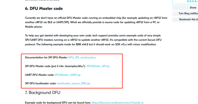
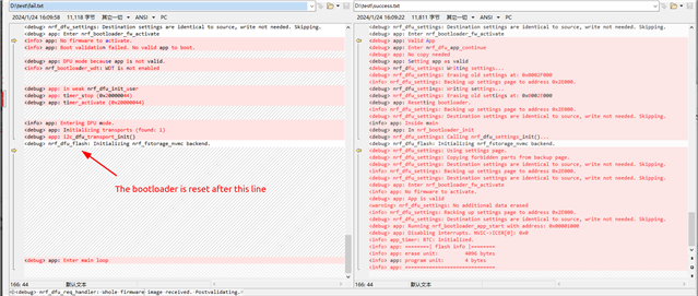
DFU (DFU-UART) is required. Due to project requirements, UART in bootloader is changed to IIC for DFU upgrade. A problem is that only the j-link RTT Viewer can successfully verify the HASH value.log Compare the following screenshot:

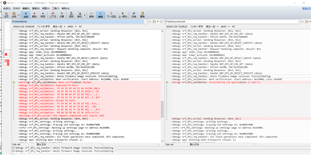
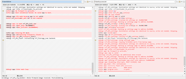
The current test outputs log information from the UART. j-link RTT Viewer selects Connection or no connection (If the chip is not connected, the HASH verification fails)

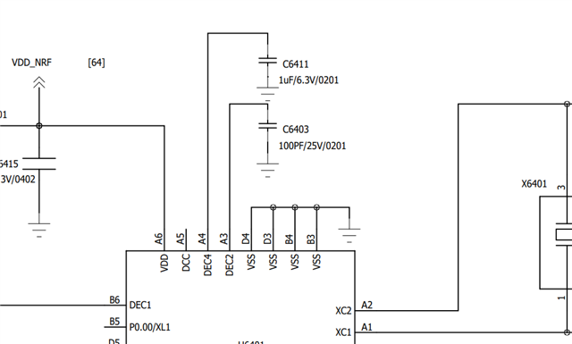
From UART to IIC, the following changes have been made:

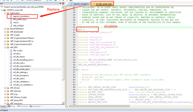
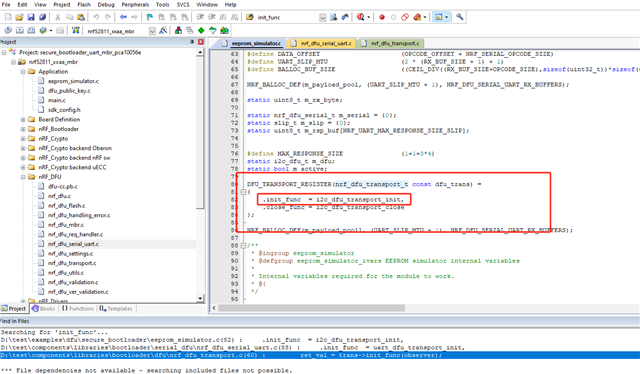
Have been looking for a long time the cause of the problem, 52811_DFU.zip is the original program used for development.
Please take a look at the cause of this problem. Thank you very much!

52811_DFU.zip

Best regards

Stars

Parents
  • Hi Stars,

    Please correct me if I'm wrong, but do I understand correctly that the bootloader only succeeds in retrieving the firmware image from your EEPROM device when the JLink RTTViewer is connected? In other words, does everything work as long as you are viewing the RTT logs? Does starting a debug session in Keil have the same effect?

    Best regards,

    Vidar

  • Hi Vidar,

    Yes, you understand correctly, the HASH will only check if the JLink RTTViewer is connected (regardless of whether the log is output from RTT or not, because the log is also tested for output from UART, the same phenomenon).
    We'll test the way to start debugging in keil.

    Update a test case. When the IIC speed drops to 100K, the IIC can be upgraded without connecting to the JLink RTTViewer. In other words, the HASH check is successful.

    Does the bootloader verify after the transfer is complete? If one of the packages fails, there is no error check inside, only the final HASH check, because I checked the reference code on the host side, each package seems to be sent without checking (program is: DFUMaster_SPI - downloaded in the connection given at the beginning)

    I can't understand the relationship between IIC rate, data clutter, and whether j-link is connected to the SWD port.

    Best regards

    Stars

  • Hi Starts,

    This suggests that DFU works when the chip is in Debug Interface mode for some reason. The bootloader is being reset here:   

    Please read out the RESETREAS register after this reset to find the reset source. You can use nrfjprog for this. E.g., 

    $ nrfjprog --memrd 0x40000400

    If it shows a lockup reset, then it may be similar to the problem discussed in this thread:  RE: Wierd hardfault  

    Best regards,

    Vidar

  • Hi Vidar,

    Thank you so much for your guidance. TASKS_CONSTLAT = 1; The setup solved the problem.

    But nrfjprog --memrd 0x40000400 reads not lockup, but SREQ:

    RE: Wierd hardfault:It is speculated that the capacitor charge/discharge speed is not fast enough, resulting in the clock/power rail does not meet the requirements. However, the current design is completely based on the parameters selected by the reference circuit diagram (the equipment works at 1.8V VCC).

    QC26C_QCM4490_DVT2_2023_1008_1600_BLE.pdf

    The VCC was increased to 2V for testing, and the IIC was upgraded normally at 400K, confirming this conjecture. But using TASKS_CONSTLAT = 1; The power consumption to enter constant delay mode is very high, and the VCC needs to operate at 1.8V.

    Is it possible to reduce the capacitance of the reference circuit so that this reduction in charge and discharge time can help us solve the problem? Or can you recommend how we can design to meet the normal operation of 1.8V VCC?

    Best regards

    Stars

  • Hi Stars,

    It seems that the issue could be related to the voltage supply in your case. Have you measured your 1.8V supply under load to ensure that it does not drop below the min. supply voltage (1.7V) when the CPU and EEPROM are running? 

    Is it possible to reduce the capacitance of the reference circuit so that this reduction in charge and discharge time can help us solve the problem? Or can you recommend how we can design to meet the normal operation of 1.8V VCC?

    I don't think you are facing the same problem as the other user. The chip is characterizied and verified with the component values used in the reference circuit.

    Does your design include the optional DCDC inductors? In that case, you could try enabling the DCDC regulator in your bootloader to reduce the peak currents.

    Best regards,

    Vidar

    Edit: Another troubleshooting step could be to replace the calls to NVIC_SystemReset() in the bootloader with while(1){}. Then, attach a debugger to your board after the bootloader gets stuck in the loop. This may help you determine the source of the reset. Maybe it's caused by an error in the IIC communication.

  • Hi Vidar,

    1.8V comes from a DC regulated power supply:

    However, in the test, it was normal when the VCC was 2V. Doesn't this reduce the capacitor charge.

    We don't have DCDC inductors:

    • Another troubleshooting step could be to replace the calls to NVIC_SystemReset() in the bootloader with while(1){}. Then, attach a debugger to your board after the bootloader gets stuck in the loop. This may help you determine the source of the reset. Maybe it's caused by an error in the IIC communication.

    That's a suggestion we'll put to the test.

    Best regards

    Stars

  • Hi Stars,

    I don't think your bench supply should have any problems handling this load, but it might be good to measure the supply voltage using an oscilloscope to confirm that the voltage remains stable and accurate throughout the DFU process. Also, maybe double check if you are meeting the min. voltage requirement for your EEPROM.

    stars said:
    That's a suggestion we'll put to the test.

    Sounds good. Thanks.

    Best regards,

    Vidar

Reply
  • Hi Stars,

    I don't think your bench supply should have any problems handling this load, but it might be good to measure the supply voltage using an oscilloscope to confirm that the voltage remains stable and accurate throughout the DFU process. Also, maybe double check if you are meeting the min. voltage requirement for your EEPROM.

    stars said:
    That's a suggestion we'll put to the test.

    Sounds good. Thanks.

    Best regards,

    Vidar

Children
Related