NRF52840 Chip- Antenna Design

Hello,

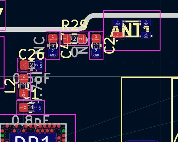
I am currently in the process of creating a custom pcb with chip antenna. I have taken the schematic from the nrf9160-dk as a reference. I would use the same components, but leave out the coaxial socket.

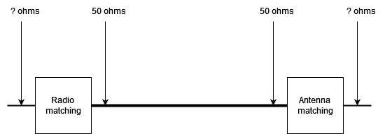
My question is: How do I calculate the transmission line? I am familiar with the calculator in kicad, but I don't know what to enter as length? Where does the transmission line start and end?Theoretically, I would lay out the transmission line from c30 to c31, but there is still the F1 filter in between.

Why are other values taken for C29 and C30 as in the referece cicuit of the nrf52840?

 Refernce circuit from nrf9160-dk:

Refernce circuit from datasheet nrf52840:

Datasheet Antenna 2450AT18D0100  The antenna datasheet does not specify any values for a matching cicuit.

Parents
  • Hi, Janik.

    My question is: How do I calculate the transmission line? I am familiar with the calculator in kicad, but I don't know what to enter as length? Where does the transmission line start and end?Theoretically, I would lay out the transmission line from c30 to c31, but there is still the F1 filter in between.

    If your transmission line has a 50-ohm impedance, the length really shouldn't have much to say. You can ask your PCB manufacturer to make sure all the numbers you have for your PCB are correct.

    janik said:
    Can I leave out the filter?

    Yes, it is. The extra filter is there to protect the radio of the nRF52840 from the output of the nRF9160 LTE modem.

    Why are other values taken for C29 and C30 as in the referece cicuit of the nrf52840?

    These values depend on PCB stackup etc. Thus, they are likely to change during the tuning process anyway.

    The antenna datasheet does not specify any values for a matching cicuit.

    You can just make sure to add the footprints and use two N.C. shunt components and one 0R series component for now. Then the values are found when we do the tuning of the antenna.

    Best regards,
    Mathias

Reply
  • Hi, Janik.

    My question is: How do I calculate the transmission line? I am familiar with the calculator in kicad, but I don't know what to enter as length? Where does the transmission line start and end?Theoretically, I would lay out the transmission line from c30 to c31, but there is still the F1 filter in between.

    If your transmission line has a 50-ohm impedance, the length really shouldn't have much to say. You can ask your PCB manufacturer to make sure all the numbers you have for your PCB are correct.

    janik said:
    Can I leave out the filter?

    Yes, it is. The extra filter is there to protect the radio of the nRF52840 from the output of the nRF9160 LTE modem.

    Why are other values taken for C29 and C30 as in the referece cicuit of the nrf52840?

    These values depend on PCB stackup etc. Thus, they are likely to change during the tuning process anyway.

    The antenna datasheet does not specify any values for a matching cicuit.

    You can just make sure to add the footprints and use two N.C. shunt components and one 0R series component for now. Then the values are found when we do the tuning of the antenna.

    Best regards,
    Mathias

Children
Related