Start PWMs synchronous

Hello there,

I have configured the 4 PWM peripherals to generate a certain waveform. I need to start all 4 pwm peripherals simultaneous.

I thought of achieving this through usage of the PPI + EGU.
EGU channel 0 event triggers EGU channel 1 and channel 2 tasks.

EGU channel 1 event triggers PWM0/1 SEQSTART tasks.

EGU channel 2 event triggers PWM2/3 SEQSTART tasks.

This is written in the code below:

static void setup_ppi(nrf_ppi_channel_t *channel, uint32_t event, uint32_t task1, uint32_t task2)
{
    nrfx_err_t err = nrfx_ppi_channel_alloc(channel);
    assert(err == NRFX_SUCCESS);
    err = nrfx_ppi_channel_assign(*channel, event, task1);
    assert(err == NRFX_SUCCESS);
    err = nrfx_ppi_channel_fork_assign(*channel, task2);
    assert(err == NRFX_SUCCESS);
    err = nrfx_ppi_channel_enable(*channel);
    assert(err == NRFX_SUCCESS);
}

static void start_pwms(const nrfx_pwm_t *pwms)
{
    nrf_ppi_channel_t channel[3];

    setup_ppi(&channel[0], nrf_egu_event_address_get(NRF_EGU0, NRF_EGU_EVENT_TRIGGERED0),
              nrf_egu_task_address_get(NRF_EGU0, NRF_EGU_TASK_TRIGGER1),
              nrf_egu_task_address_get(NRF_EGU0, NRF_EGU_TASK_TRIGGER2));
    setup_ppi(&channel[1], nrf_egu_event_address_get(NRF_EGU0, NRF_EGU_EVENT_TRIGGERED1),
              nrfx_pwm_task_address_get(&pwms[0], NRF_PWM_TASK_SEQSTART1),
              nrfx_pwm_task_address_get(&pwms[1], NRF_PWM_TASK_SEQSTART1));
    setup_ppi(&channel[2], nrf_egu_event_address_get(NRF_EGU0, NRF_EGU_EVENT_TRIGGERED2),
              nrfx_pwm_task_address_get(&pwms[2], NRF_PWM_TASK_SEQSTART1),
              nrfx_pwm_task_address_get(&pwms[3], NRF_PWM_TASK_SEQSTART1));

    nrf_egu_task_trigger(NRF_EGU0, NRF_EGU_TASK_TRIGGER0);

    for (size_t k = 0; k < ARRAY_SIZE(channel); k++) {
        nrfx_err_t err = nrfx_ppi_channel_free(channel[k]);
        assert(NRFX_SUCCESS == err);
    }
}

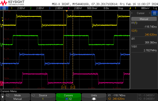
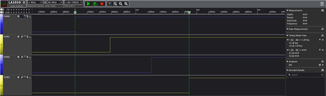
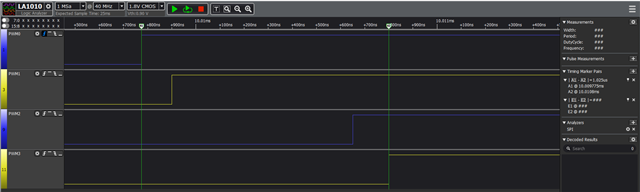
The following 4 signals should rise at the same time, however they are 1.85 us out of sync.


Triggering the PWM SEQSTART tasks manually has the same result:

    nrf_pwm_task_trigger(NRF_PWM0, NRF_PWM_TASK_SEQSTART1);
    nrf_pwm_task_trigger(NRF_PWM1, NRF_PWM_TASK_SEQSTART1);
    nrf_pwm_task_trigger(NRF_PWM2, NRF_PWM_TASK_SEQSTART1);
    nrf_pwm_task_trigger(NRF_PWM3, NRF_PWM_TASK_SEQSTART1);

Strangely enough, if I reverse the order in which I start the PWMS:

    nrf_pwm_task_trigger(NRF_PWM3, NRF_PWM_TASK_SEQSTART1);
    nrf_pwm_task_trigger(NRF_PWM2, NRF_PWM_TASK_SEQSTART1);
    nrf_pwm_task_trigger(NRF_PWM1, NRF_PWM_TASK_SEQSTART1);
    nrf_pwm_task_trigger(NRF_PWM0, NRF_PWM_TASK_SEQSTART1);

The PWM signals are still generated in order PWM0->PWM3


Can anyone explain this? Is there no way to start the PWMs at the same time?

I am using NCS V2.5.0.

  • I have tried this code and there is still delay between the PWM peripherals.

  • You may be observing an artifact on the logic analyser sampling mode; do you have a high-bandwidth oscilloscope available?

  • The LA1010 is only a 20MHz logic analyzer with typically 40MHz sampling - this is nowhere near good enough to measure the offset correctly. I tested this code with a 300MHz oscilloscope at 2GHz sampling and there is no measurable phase offset as shown on traces included earlier with no loading on the pins. You may be observing an artifact on the logic analyser sampling mode

  • You can improve the LA1010 logic analyser performance by reducing the slope on the PWM output signals, high-drive H0H1 helps with this:

    static void EnableExtClockPWM(NRF_PWM_Type * const pPWM, const uint32_t PWM_Pin)
    {
       // Set pins to output ports first, high drive to get sharpest edges, driving low
       nrf_gpio_pin_clear(PWM_Pin);
       // Configuration      Direction                Input                          Pullup               Drive Level        Sense Level
       // =================  =======================  =============================  ===================  =================  =====================
       nrf_gpio_cfg(PWM_Pin, NRF_GPIO_PIN_DIR_OUTPUT, NRF_GPIO_PIN_INPUT_DISCONNECT, NRF_GPIO_PIN_NOPULL, NRF_GPIO_PIN_H0H1, NRF_GPIO_PIN_NOSENSE);
    
       pPWM->PSEL.OUT[0] = (PWM_Pin  << PWM_PSEL_OUT_PIN_Pos) | (PWM_PSEL_OUT_CONNECT_Connected << PWM_PSEL_OUT_CONNECT_Pos);
       pPWM->ENABLE      = (PWM_ENABLE_ENABLE_Enabled << PWM_ENABLE_ENABLE_Pos);
       pPWM->MODE        = (PWM_MODE_UPDOWN_Up << PWM_MODE_UPDOWN_Pos);
       pPWM->PRESCALER   = (PWM_PRESCALER_PRESCALER_DIV_2 << PWM_PRESCALER_PRESCALER_Pos);
       pPWM->COUNTERTOP  = ((PWM_CH0_DUTY*2) << PWM_COUNTERTOP_COUNTERTOP_Pos);
       pPWM->LOOP        = 10;
       pPWM->DECODER     = (PWM_DECODER_LOAD_Grouped << PWM_DECODER_LOAD_Pos) | (PWM_DECODER_MODE_RefreshCount << PWM_DECODER_MODE_Pos);
       pPWM->SEQ[0].PTR  = ((uint32_t)(pwm_seq) << PWM_SEQ_PTR_PTR_Pos);
       pPWM->SEQ[0].CNT  = ((sizeof(pwm_seq) / sizeof(uint16_t)) << PWM_SEQ_CNT_CNT_Pos);
       pPWM->SEQ[0].REFRESH  = 0;
       pPWM->SEQ[0].ENDDELAY = 0;
    }

  • This was measured with an InfiniVision MSO-X 3024T (200 MHz, 5GSa/s).
    I also changed the signals to high-drive (but this did not seem change much) :/

Related