Improving the Timing of Output Compare

Hello, I am currently trying to program a WS2812B LED matrix using output compare. There's 256 LEDs, and each LED is controlled by 24 bits. However, it has somewhat strict timing requirements, and my current code is not efficient enough. The LEDs are resetting after about half of the LEDs are lit up. I am new to programming and I am wondering if I can get some advice on how I can improve my code or improve the timing? Thank you!

#include <stdbool.h>
#include <stdint.h>

void outputBit(int value) {
  if (value == 1) {
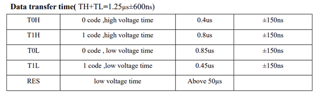
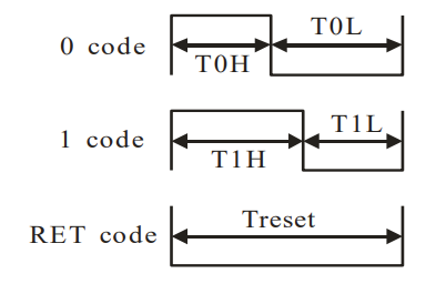
    /* Pin high for approx. 0.8 us, then go low for 0.45 us */
    NRF_P0->OUTSET = (1UL << 27); // Set pin to high

    NRF_TIMER0->CC[0] = 6;
    NRF_TIMER0->TASKS_START = 1;  // Starts the clock signal
    while (!(NRF_TIMER0->EVENTS_COMPARE[0])); // Wait for event to occur
    NRF_TIMER0->TASKS_STOP = 1; // Starts the clock signal

    NRF_TIMER0->CC[0] = 4;
    NRF_TIMER0->EVENTS_COMPARE[0] = 0; // Clear the event
    NRF_TIMER0->TASKS_START = 1;       // Starts the clock signal
    while (!(NRF_TIMER0->EVENTS_COMPARE[0])); // Wait for event to occur
    NRF_TIMER0->TASKS_STOP = 1;        // Starts the clock signal
    NRF_TIMER0->EVENTS_COMPARE[0] = 0; // Clear the event
  } else {
    /* Pin high for approx. 0.35 us, then go low for 0.85 us */
    NRF_P0->OUTSET = (1UL << 27); // Set pin to high

    NRF_TIMER0->CC[0] = 3;
    NRF_TIMER0->TASKS_START = 1;  // Starts the clock signal
    while (!(NRF_TIMER0->EVENTS_COMPARE[0])); // Wait for event to occur
    NRF_TIMER0->TASKS_STOP = 1; // Starts the clock signal

    NRF_TIMER0->CC[0] = 7;
    NRF_TIMER0->EVENTS_COMPARE[0] = 0; // Clear the event
    NRF_TIMER0->TASKS_START = 1;       // Starts the clock signal
    while (!(NRF_TIMER0->EVENTS_COMPARE[0])); // Wait for event to occur
    NRF_TIMER0->TASKS_STOP = 1;        // Starts the clock signal
    NRF_TIMER0->EVENTS_COMPARE[0] = 0; // Clear the event
  }
}

int main(void) {
  NRF_P0->PIN_CNF[27] = (GPIO_PIN_CNF_DIR_Output << GPIO_PIN_CNF_DIR_Pos) |
                        (GPIO_PIN_CNF_DRIVE_S0S1 << GPIO_PIN_CNF_DRIVE_Pos) |
                        (GPIO_PIN_CNF_INPUT_Connect << GPIO_PIN_CNF_INPUT_Pos) |
                        (GPIO_PIN_CNF_PULL_Disabled << GPIO_PIN_CNF_PULL_Pos) |
                        (GPIO_PIN_CNF_SENSE_Disabled << GPIO_PIN_CNF_SENSE_Pos);

  // Enable high frequency oscillator if not already enabled
  if (NRF_CLOCK->EVENTS_HFCLKSTARTED == 0) {
    NRF_CLOCK->TASKS_HFCLKSTART = 1;
    while (NRF_CLOCK->EVENTS_HFCLKSTARTED == 0) {
    }
  }

  NRF_TIMER0->PRESCALER = 1; // 8MHz
  NRF_TIMER0->BITMODE = 0;
  NRF_TIMER0->SHORTS |= (1UL << 0); // Automatically clear the count whenever an event is triggered

  NRF_GPIOTE->CONFIG[0] = GPIOTE_CONFIG_MODE_Task | (27 << GPIOTE_CONFIG_PSEL_Pos) |
      (GPIOTE_CONFIG_POLARITY_Toggle << GPIOTE_CONFIG_POLARITY_Pos);

  /*Connect TIMER event to GPIOTE out task*/
  NRF_PPI->CH[0].EEP = (uint32_t)&NRF_TIMER0->EVENTS_COMPARE[0];
  NRF_PPI->CH[0].TEP = (uint32_t)&NRF_GPIOTE->TASKS_OUT[0];
  NRF_PPI->CHENSET |= (1UL << 0);

  NRF_TIMER0->EVENTS_COMPARE[0] = 0; // Clear the event

  for (int i = 0; i < 6144; ++i) {
    outputBit(1);
  }
}

Parents
  • Hello,

    I see that there are a lot of posts here on DevZone regarding controlling the WS2812B using the nRF5 series chips, so if you are stuck, I guess you can look into some of them. However, most of them are using I2C or SPI in a way that works with these LEDs. But this should work as well.

    You have already figured out most of this, using the PPI with a timer and GPIOTE. If you see that this is unstable, my guess is that you see this beause you stop the timer after every EVENTS_COMPARE. You can utilize the fact that the TIMER0 on the nRF52840 has 4 Capture Compare (CC) registers. In addition, I would try to set the GPIO specifically high or low, instead of toggling, just in case you misse an event at some point, in which case you may end up with a flipped signal. 

    I tried to test this, but it looks like it is still too slow when setting the GPIO manually before starting the timer, so I think I need to add a 3rd CC register to set it high just at the start of the signal. Unfortunately, I didn't have time to do it today. I will attach what I have, and you can play around with it and see if you can make it work. Please let me know if it doesn't.

    #define GPIO_WS2812B_CHANNEL    0           // GPIO channel used for configuration
    #define GPIO_WS2812B_PIN        3           // P0.03
    #define PPI_CH_A                0
    #define PPI_CH_B                1
    #define OUT_LOW_CC              0
    #define OUT_HIGH_CC             1
    #define TIMER_RELOAD_CC_NUM     OUT_HIGH_CC // The timer will reset the counter (without stopping) when this CC register is reached.
    
    void timer_init(void)
    {
        NRF_CLOCK->TASKS_HFCLKSTART=1;
        while (!NRF_CLOCK->EVENTS_HFCLKSTARTED){
            // Wait
        }
        NRF_TIMER3->PRESCALER = 0; // 16MHz for better accuracy.
        NRF_TIMER3->BITMODE = TIMER_MODE_MODE_Timer << TIMER_MODE_MODE_Pos;
        NRF_TIMER3->SHORTS = TIMER_SHORTS_COMPARE0_CLEAR_Msk << TIMER_RELOAD_CC_NUM;
        // (1UL << 0); // Automatically clear the count whenever an event is triggered
    }
    
    void gpio_ppi_init(void)
    {
        // Set up GPIO:
        NRF_GPIOTE->CONFIG[GPIO_WS2812B_CHANNEL]  = GPIOTE_CONFIG_MODE_Task << GPIOTE_CONFIG_MODE_Pos | 
                                                    GPIOTE_CONFIG_POLARITY_Toggle << GPIOTE_CONFIG_POLARITY_Pos | 
                                                    GPIO_WS2812B_PIN << GPIOTE_CONFIG_PSEL_Pos | 
                                                    GPIOTE_CONFIG_OUTINIT_High << GPIOTE_CONFIG_OUTINIT_Pos;
        // Set up PPI:
        NRF_PPI->CH[PPI_CH_A].EEP   = (uint32_t)&NRF_TIMER3->EVENTS_COMPARE[OUT_LOW_CC];
        NRF_PPI->CH[PPI_CH_A].TEP   = (uint32_t)&NRF_GPIOTE->TASKS_CLR[GPIO_WS2812B_CHANNEL];
    
        NRF_PPI->CH[PPI_CH_B].EEP   = (uint32_t)&NRF_TIMER3->EVENTS_COMPARE[OUT_HIGH_CC];
        NRF_PPI->CH[PPI_CH_B].TEP   = (uint32_t)&NRF_GPIOTE->TASKS_SET[GPIO_WS2812B_CHANNEL];
        NRF_PPI->FORK[PPI_CH_B].TEP = (uint32_t)&NRF_TIMER3->TASKS_STOP;
    
        NRF_PPI->CHENSET            = (1 << PPI_CH_A) | (1 << PPI_CH_B);
    }
    
    void run_t0(void)
    {
        // Set sequence:
        // 1 timer tick (16MHz) = 0.0625 µs, 0.4 µs  = 6.4  ticks (6  ticks = 0,375 µs)
        NRF_TIMER3->CC[OUT_LOW_CC]  = 6;
        // 1 timer tick (16MHz) = 0.0625 µs, 0.85 µs = 13.6 ticks (14 ticks = 0.875 µs)
        NRF_TIMER3->CC[OUT_HIGH_CC] = 14;
        // Start:
        NRF_TIMER3->TASKS_CLEAR = 1;                    // Clear timer before start.
        NRF_GPIOTE->TASKS_SET[GPIO_WS2812B_CHANNEL]=1;  // set output high for start signal.
        NRF_TIMER3->TASKS_START=1;                      // Start timer.
    
        while (!(NRF_TIMER3->EVENTS_COMPARE[TIMER_RELOAD_CC_NUM]));
        NRF_TIMER3->TASKS_STOP = 1;
    
    }
    
    
    int main(void)
    {
        int ret;
        // printk("my_gpio_pin psel %d\n", my_gpio_pin);
        
    
        timer_init();
        gpio_ppi_init();
        NRF_GPIOTE->TASKS_CLR[GPIO_WS2812B_CHANNEL]=1;  // set output high for start signal.
        k_sleep(K_MSEC(200));
        run_t0();

    Note that this was written in NCS (Zephyr). It looks like you were using the nRF5 SDK. Just replace the k_sleep() with nrf_delay_ms(), or remove it.

    Best regards,

    Edvin

  • Hi Edvin,

    Thank you for the help!

    I've been playing with your code for a few days now and I think I am close to getting it work reliably, but it's not there yet.

    I am now trying to take a slightly different approach by using different timers depending on whether I need to output a 1 or 0. Attached is my code so far.

    I am new to programming and I am wondering if I can get some advice on how I can improve the reliability and timing of my code? 

    Thank you!

    #define GPIO_WS2812B_CHANNEL    0           // GPIO channel used for configuration
    #define GPIO_WS2812B_PIN        27          // P0.27
    #define PPI_CH_A                0
    #define PPI_CH_B                1
    #define PPI_CH_C                2
    #define PPI_CH_D                3
    #define OUT_HIGH_CC             0
    #define OUT_LOW_CC              1
    #define TIMER_RELOAD_CC_NUM     OUT_LOW_CC // The timer will reset the counter (without stopping) when this CC register is reached.
    
    void timer_init(void)
    {
        NRF_CLOCK->TASKS_HFCLKSTART=1;
        while (!NRF_CLOCK->EVENTS_HFCLKSTARTED){
            // Wait
        }
        NRF_TIMER3->PRESCALER = 0; // 16MHz for better accuracy.
        NRF_TIMER3->BITMODE = TIMER_MODE_MODE_Timer << TIMER_MODE_MODE_Pos;
        NRF_TIMER3->SHORTS = TIMER_SHORTS_COMPARE0_CLEAR_Msk << TIMER_RELOAD_CC_NUM;
        // (1UL << 0); // Automatically clear the count whenever an event is triggered
    
        NRF_TIMER4->PRESCALER = 0; // 16MHz for better accuracy.
        NRF_TIMER4->BITMODE = TIMER_MODE_MODE_Timer << TIMER_MODE_MODE_Pos;
        NRF_TIMER4->SHORTS = TIMER_SHORTS_COMPARE0_CLEAR_Msk << TIMER_RELOAD_CC_NUM;
    }
    
    void gpio_ppi_init(void)
    {
        // Set sequence:
        // High for 14 ticks, toggle, then go low for 4 ticks, toggle
        // 1 timer tick (16MHz) = 0.0625 µs, 0.85 µs = 13.6 ticks (14 ticks = 0.875 µs)
        // 1 timer tick (16MHz) = 0.0625 µs, 0.4 µs  = 6.4  ticks (6  ticks = 0,375 µs)
        NRF_TIMER3->CC[OUT_HIGH_CC]  = 14;
        NRF_TIMER3->CC[OUT_LOW_CC] = 20; //Toggle from low to high after 20 ticks (14 ticks high, 6 ticks low)
        
        // Set up GPIO:
        NRF_GPIOTE->CONFIG[GPIO_WS2812B_CHANNEL]  = GPIOTE_CONFIG_MODE_Task << GPIOTE_CONFIG_MODE_Pos | 
                                                    GPIOTE_CONFIG_POLARITY_Toggle << GPIOTE_CONFIG_POLARITY_Pos | 
                                                    GPIO_WS2812B_PIN << GPIOTE_CONFIG_PSEL_Pos | 
                                                    GPIOTE_CONFIG_OUTINIT_High << GPIOTE_CONFIG_OUTINIT_Pos;
        // Set up PPI:
        NRF_PPI->CH[PPI_CH_A].EEP   = (uint32_t)&NRF_TIMER3->EVENTS_COMPARE[OUT_LOW_CC];
        NRF_PPI->CH[PPI_CH_A].TEP   = (uint32_t)&NRF_GPIOTE->TASKS_CLR[GPIO_WS2812B_CHANNEL];
    
        NRF_PPI->CH[PPI_CH_B].EEP   = (uint32_t)&NRF_TIMER3->EVENTS_COMPARE[OUT_HIGH_CC];
        NRF_PPI->CH[PPI_CH_B].TEP   = (uint32_t)&NRF_GPIOTE->TASKS_SET[GPIO_WS2812B_CHANNEL];
        NRF_PPI->FORK[PPI_CH_B].TEP = (uint32_t)&NRF_TIMER3->TASKS_STOP;
    
        NRF_TIMER3->TASKS_CLEAR = 1;                    // Clear timer before start.
    
        // Set sequence:
        // High for 6 ticks, toggle, then go low for 14 ticks, toggle
        // 1 timer tick (16MHz) = 0.0625 µs, 0.4 µs  = 6.4  ticks (6  ticks = 0,375 µs)
        // 1 timer tick (16MHz) = 0.0625 µs, 0.85 µs = 13.6 ticks (14 ticks = 0.875 µs)
        NRF_TIMER4->CC[OUT_HIGH_CC]  = 6;
        NRF_TIMER4->CC[OUT_LOW_CC] = 20;
        
        // Set up PPI:
        NRF_PPI->CH[PPI_CH_C].EEP   = (uint32_t)&NRF_TIMER4->EVENTS_COMPARE[OUT_LOW_CC];
        NRF_PPI->CH[PPI_CH_C].TEP   = (uint32_t)&NRF_GPIOTE->TASKS_CLR[GPIO_WS2812B_CHANNEL];
    
        NRF_PPI->CH[PPI_CH_D].EEP   = (uint32_t)&NRF_TIMER4->EVENTS_COMPARE[OUT_HIGH_CC];
        NRF_PPI->CH[PPI_CH_D].TEP   = (uint32_t)&NRF_GPIOTE->TASKS_SET[GPIO_WS2812B_CHANNEL];
        NRF_PPI->FORK[PPI_CH_D].TEP = (uint32_t)&NRF_TIMER4->TASKS_STOP;
    
        NRF_PPI->CHENSET            = (1 << PPI_CH_A) | (1 << PPI_CH_B) | (1 << PPI_CH_C) | (1 << PPI_CH_D);
    
        NRF_TIMER4->TASKS_CLEAR = 1;                    // Clear timer before start.
    }
    
    
    void run_bit0(void)
    {
        NRF_TIMER4->TASKS_START = 1;                      // Start timer.
    
        while (!(NRF_TIMER4->EVENTS_COMPARE[TIMER_RELOAD_CC_NUM]));
        NRF_TIMER4->TASKS_STOP = 1;
        NRF_TIMER4->EVENTS_COMPARE[OUT_HIGH_CC] = 0; // Clear the event
        NRF_TIMER4->EVENTS_COMPARE[OUT_LOW_CC] = 0; // Clear the event
    }
    
    void run_bit1(void)
    {
        NRF_TIMER3->TASKS_START = 1;                      // Start timer.
    
        while (!(NRF_TIMER3->EVENTS_COMPARE[TIMER_RELOAD_CC_NUM]));
        NRF_TIMER3->TASKS_STOP = 1;
        NRF_TIMER3->EVENTS_COMPARE[OUT_HIGH_CC] = 0; // Clear the event
        NRF_TIMER3->EVENTS_COMPARE[OUT_LOW_CC] = 0; // Clear the event
    }
    
    
    int main(void)
    {
        int ret;
        // printk("my_gpio_pin psel %d\n", my_gpio_pin);
        
    
        timer_init();
        gpio_ppi_init();
        NRF_GPIOTE->TASKS_CLR[GPIO_WS2812B_CHANNEL] = 1;  // set output high for start signal.
        NRF_GPIOTE->TASKS_SET[GPIO_WS2812B_CHANNEL]=1;  // set output high for start signal.
        k_sleep(K_MSEC(200));
        for(int i = 0; i < 3072; ++i){
          run_bit1();
          run_bit0();
        }
    }

  • Hello,

    Do you have a logic analyzer? If so, can you try to capture a trace of the pin?

    I don't have an LED strip to test on, and I am not sure exactly how the pin is supposed to behave in between the bit signals. All signals end up on the pin high, but can it stay high as long as you like, or does it need to continue immediately? (since they specify how long  the pin should be high inside the bit signal). 

    The signal is quite fast (only a handful of ticks on every state), so whenever it needs to wait for the CPU to run the next bit signal, a lot of time passes (relatively). Therefore I am curious as to whether this PPI approach is the way to go or not. It may be better to use something like an SPI instance, where you can modify the payload so that the MOSI pin acts like this. By using e.g. an SPI bus, you can load the configuration into an SPI buffer, and it will just pump out the data without stop, and without the need to wait for the CPU.

    I don't have an SPI sample at hand right now. You can search around on DevZone, and let me know if you can't find any.

    Best regards,

    Edvin

Reply
  • Hello,

    Do you have a logic analyzer? If so, can you try to capture a trace of the pin?

    I don't have an LED strip to test on, and I am not sure exactly how the pin is supposed to behave in between the bit signals. All signals end up on the pin high, but can it stay high as long as you like, or does it need to continue immediately? (since they specify how long  the pin should be high inside the bit signal). 

    The signal is quite fast (only a handful of ticks on every state), so whenever it needs to wait for the CPU to run the next bit signal, a lot of time passes (relatively). Therefore I am curious as to whether this PPI approach is the way to go or not. It may be better to use something like an SPI instance, where you can modify the payload so that the MOSI pin acts like this. By using e.g. an SPI bus, you can load the configuration into an SPI buffer, and it will just pump out the data without stop, and without the need to wait for the CPU.

    I don't have an SPI sample at hand right now. You can search around on DevZone, and let me know if you can't find any.

    Best regards,

    Edvin

Children
Related