NFC Pins drive strength and configuration

Hello all,

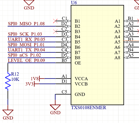
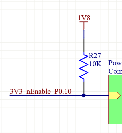
I'm trying to use pins NFC1 and NFC2 to drive a pulldown 10K resistor and a pullup 10K resistor respectively. The NRF chip is the 52840, mounted on a u-blox SiP. The chip is driven with 1.8V instead of the usual 3.3 due to some design restrictions. One output enables a TI level translator, the other enables a power chip (inverted logic). Default is pull down for the level translator, pull up for the power converter.

The connections are as follows:

Both signals are routed through middle layers (4 layer PCB).

The signals were configured using the following DTS entries:

        enable_lines {
            compatible = "gpio-leds";
    
            level_enable: level_enable{
                gpios = < &gpio0 9 GPIO_ACTIVE_HIGH>;
            };
    
            3v3_nenable: 3v3_nenable{
                gpios = < &gpio0 10 GPIO_ACTIVE_HIGH>;
            };
        };

To test, these signals were initialised at the "enable" level for both, '1' for the level converter and '0' for the power supply.

To my surprise, after boot, both signals were still pulled up or down, as if the resistor proved to strong for them. I measured the resistor in each case and both were about 10K (a little below perhaps). I removed those resistors and the levels were working correctly.

I can't imagine that a 10K pullup or down is too strong for an output pin, but I do realise these are NFC pins so perhaps I'm missing some configuration? I will try to change to other pins on the next hardware revision, but for this one it would be good to find a solution to drive the 10K properly.

Any help is appreciated.

Cheers,

Alberto

Parents
  • Hi Jared,

    this is the printout when I look at all P0 registers, with GPIO09 and GPIO10:

    [00:00:00.000,366] <inf> leds: Initialising LEDs
    [00:00:00.000,396] <inf> leds: GPIO0.OUT: 0x00000210
    [00:00:00.000,427] <inf> leds: GPIO0.OUTSET: 0x00000210
    [00:00:00.000,427] <inf> leds: GPIO0.OUTCLR: 0x00000210
    [00:00:00.000,427] <inf> leds: GPIO0.IN: 0x08040000
    [00:00:00.000,457] <inf> leds: GPIO0.DIR: 0x04000650
    [00:00:00.000,457] <inf> leds: GPIO0.DIRSET: 0x04000650
    [00:00:00.000,488] <inf> leds: GPIO0.DIRCLR: 0x04000650
    [00:00:00.000,488] <inf> leds: GPIO0.LATCH: 0x00000000
    [00:00:00.000,518] <inf> leds: GPIO0.DETECTMODE: 0x00000000
    [00:00:00.000,518] <inf> leds: GPIO0.PIN_CNF[9]: 0x00000003
    [00:00:00.000,518] <inf> leds: GPIO0.PIN_CNF[10]: 0x00000003

    I can confirm that the resistance (pull up and down) when the board is off is 10K, but I have not measured it with the board powered. I'll investigate a bit further.

    Cheers,

    Alberto

Reply
  • Hi Jared,

    this is the printout when I look at all P0 registers, with GPIO09 and GPIO10:

    [00:00:00.000,366] <inf> leds: Initialising LEDs
    [00:00:00.000,396] <inf> leds: GPIO0.OUT: 0x00000210
    [00:00:00.000,427] <inf> leds: GPIO0.OUTSET: 0x00000210
    [00:00:00.000,427] <inf> leds: GPIO0.OUTCLR: 0x00000210
    [00:00:00.000,427] <inf> leds: GPIO0.IN: 0x08040000
    [00:00:00.000,457] <inf> leds: GPIO0.DIR: 0x04000650
    [00:00:00.000,457] <inf> leds: GPIO0.DIRSET: 0x04000650
    [00:00:00.000,488] <inf> leds: GPIO0.DIRCLR: 0x04000650
    [00:00:00.000,488] <inf> leds: GPIO0.LATCH: 0x00000000
    [00:00:00.000,518] <inf> leds: GPIO0.DETECTMODE: 0x00000000
    [00:00:00.000,518] <inf> leds: GPIO0.PIN_CNF[9]: 0x00000003
    [00:00:00.000,518] <inf> leds: GPIO0.PIN_CNF[10]: 0x00000003

    I can confirm that the resistance (pull up and down) when the board is off is 10K, but I have not measured it with the board powered. I'll investigate a bit further.

    Cheers,

    Alberto

Children
No Data
Related