I am performing a tests on nRF52840DK to measure the System ON power consumption using PPK II. For all tests, I am using blinky example. The full code:
/*
 * Copyright (c) 2016 Intel Corporation
 *
 * SPDX-License-Identifier: Apache-2.0
 */

#include <zephyr/kernel.h>
#include <zephyr/drivers/gpio.h>

/* 1000 msec = 1 sec */
#define SLEEP_TIME_MS   1000

/* The devicetree node identifier for the "led0" alias. */
#define LED0_NODE DT_ALIAS(led0)

/*
 * A build error on this line means your board is unsupported.
 * See the sample documentation for information on how to fix this.
 */
static const struct gpio_dt_spec led = GPIO_DT_SPEC_GET(LED0_NODE, gpios);

int main(void)
{
	int ret;

	if (!gpio_is_ready_dt(&led)) {
		return 0;
	}

	ret = gpio_pin_configure_dt(&led, GPIO_OUTPUT_ACTIVE);
	if (ret < 0) {
		return 0;
	}

	while (1) {
		ret = gpio_pin_toggle_dt(&led);
		if (ret < 0) {
			return 0;
		}
		k_msleep(SLEEP_TIME_MS);
	}
	return 0;
}
I have followed guide that explains how to prepare nRF52840DK for measuring current consumption using PPK II:
https://infocenter.nordicsemi.com/index.jsp?topic=%2Fug_ppk2%2FUG%2Fppk%2FPPK_user_guide_Intro.html
So I did the following:
1. Cut the SB40
2. Connect the Vin and Vout of the PPK II to P22 of the nRF52840DK
3. Connect the USB (J2) to power the nRF52840DK
4. Start the nRF Power Profiler in Ampere meter mode
TEST1
- SW6: Default mode
- nRF Power source: VDD
- nRF52840 powered through USB J2
- PPK II in Ampere mode
- USB (J2) to connected to power the DK
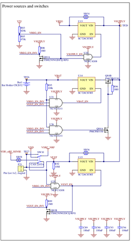
My system photo:
...
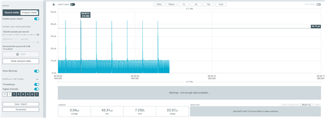
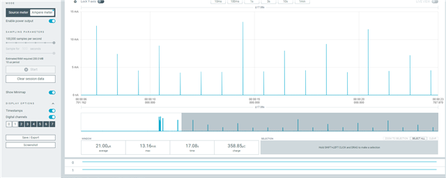
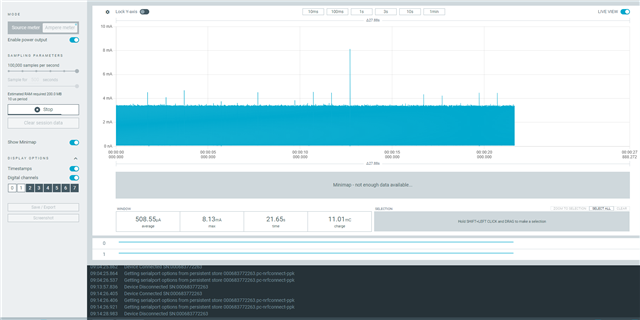
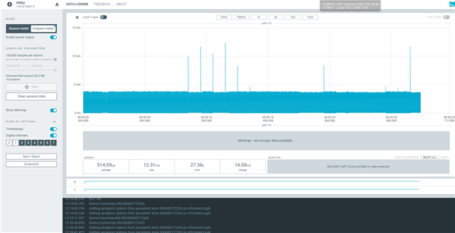
Results:
Concerns:
I was hoping to see the spikes every 1 second when the LED is turned ON but that does not seem to be the case. Additionally, there seems to be quite a bit of noise that looks like below when zoomed in:
TEST2
- SW6: nRF only mode
- nRF Power source: VDD
- nRF52840 powered through USB J2
- PPK II in Ampere mode
- USB (J2) to connected to power the DK
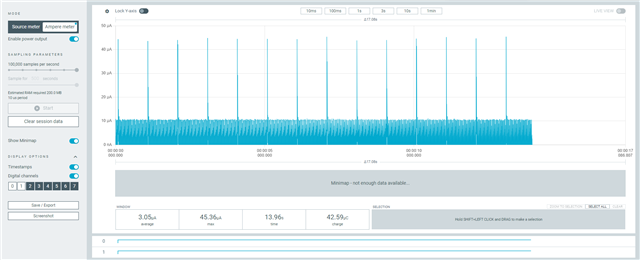
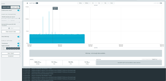
When the SW6 is put in the nRF only mode, the program does not seem to be running. After putting the switch to nRF Only position, the com port dissapeared and the LED's stopped blinking, however the Power profiler graph looks very simillar to TEST1 (slightly less current consumption).
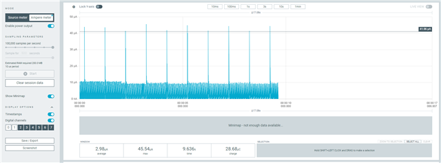
Results:
Concerns:
I have read about nRF only mode here: https://infocenter.nordicsemi.com/index.jsp?topic=%2Fug_nrf52840_dk%2FUG%2Fdk%2Fnrf_only_mode.html
But I cannot fully figure out why would the LED not be working.
TEST3
For this test, I use PPK II source mode instead of Ampere mode.
- SW6: Default mode
- nRF Power source: VDD
- nRF52840 powered by the PPK II through P21 connector
- PPK II in Source mode (3.3V)
- USB (J2) to connected to power the DK
See my system photo:
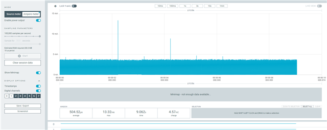
Results:
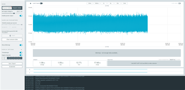
Concerns:
The device does not seem to enter low power mode (current consumption is above 1mA. Also, I am not able to notice the spikes every 1 second when the LED is turned ON.
TEST4
- SW6: nRF only mode
- nRF Power source: VDD
- nRF52840 powered by the PPK II through P21 connector
- PPK II in Source mode (3.3V)
- USB (J2) to connected to power the DK
When the SW6 is put in the nRF only mode, the program does not seem to be running. After putting the switch to nRF Only position, the com port dissapeared and the LED's stopped blinking
Result:
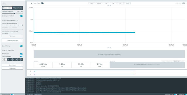
TEST5
- SW6: Default mode
- nRF Power source: VDD
- nRF52840 powered by the PPK II through P21 connector
- PPK II in Source mode (3.3V)
- USB (J2) to disconnected
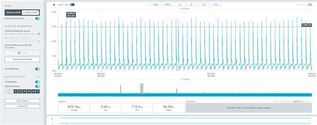
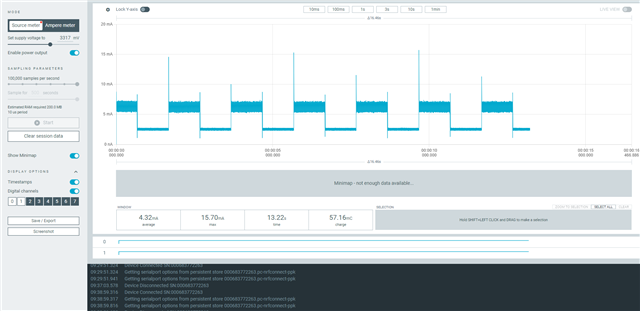
Results:
With the USB J2 disconnected, I can finally see some results that make sense. I can see the current consumption increase/decrease every 1 second when the LED is toggled
I have then tried to setup my nRF52840DK according this:
infocenter.nordicsemi.com/index.jsp
TEST6
Using Li-Po battery to power the board in addition to USB J2
- SW6: Default mode
- nRF Power source: VDD
- nRF52840 powered by the Li-po battery (3.8V)
- PPK II in Ampere meter mode
- USB (J2) to connected to DK
Results:
TEST7
Using Li-Po battery to power the board and having the USB disconnected
- SW6: Default mode
- nRF Power source: VDD
- nRF52840 powered by the Li-po battery (3.8V)
- PPK II in Ampere meter mode
- USB (J2) to disconnected
Result:
As you can see from above, I have made power consumption experiments with 7 different configurations and only one (TEST5) provided results that makes any sense.
I would like to understand what is the most optimal way to measure the current consumption of the nRF52840 as there are many variables involved and it is not fully clear.
Questions:
1. Regarding TEST1 it is not clear to me why I am not able to capture current consumption spikes when the LED turns ON. Is there a problem with the J2 USB? Should it be connected and what affect does it have? Since I use ampere meter mode, I have to power the board from an external source so I chose USB.
2. Regarding TEST2 it is very strange to me why the LED stops blinking and when the switch (SW6) is put in nRF only mode. From what I understand, the SW6 position in nRF only mode should disable the interface MCU, the debugging but everything that relates to main CPU including LED's should still function..
3. Regarding TEST3, I have used Source meter mode to externally power the device while having the USB plugged in. The current consumption is very strange and again, the LED toggling does not seem to show up on the graph.
4. Regarding TEST4, same issue that TEST2 has.. The LED stopped blinking and current consumption is quite strange... How can we explain this behaviour?
5. Regarding TEST5. Finally able to see the graph that makes some sense. The current increases/decreases at 1second intervals.. However the system does not seem to enter proper System ON low power mode when the task is idling.
6. Regarding TEST6 and TEST7 I am not fully understanding why there is no difference whether I have the USB plugged in or plugged out?
7. So what is the truly correct way to measure the nRF52840DK current consumption? I am interested in the current consumption of the nRF52840 and all peripherals connected to it (LED's and whatever other sensors that I plug in and use). For this, I assume I should use nRF only mode to ensure the Interface MCU is cut off. But as I shown in my experiments above, when using nRF only mode the cpu does not seem to run properly - the LED's wont even blink.