
How to configure nRF5340 for RF measurements. which programs can be flashed to the device to get 100% TX and 100% RX and measure the RF parameters
How to configure nRF5340 for RF measurements. which programs can be flashed to the device to get 100% TX and 100% RX and measure the RF parameters
Hi, As you can see here it does not make sense to measure both VDD_HV and VDD."
By default, the high voltage regulator is configured to source external components from the VDD pin. To save power this feature must be disabled. For details, see High voltage mode."
Is the device running in HV mode? Also, is this a custom board? I'm not sure that you would gain anything to measure the current consumption since if it is a custom boards you it can be hard to correlate power consumption with RX effect.
Regards
Runar
Hi Runar,
What did you mean by custom mode I'm using a nRF5340 DK and putting it into modes like advertisement using nRF connect in V S Code.
So my question here is at that time, which of these rails(VDD & VDD_HV) can give the chips current consumption at these modes.
Regards,
Arun
We don't have any list of which examples enters the different states. I would recommend to either use the mentioned sample as it is made for power profiling or create a sample that suits your needs. If I misunderstood you, please try to reword the question.
Regards
Runar
To use power profile, we need the power profile kit hardware right?
Regards,
Arun
As written in the link:
"
Optionally, you can use the Power Profiler Kit II (PPK2) for power profiling and optimizing your configuration. You can use also your proprietary solution for measuring the power consumption."
Regards
Runar
Hi Runar,
coming back to the topic we were discussing,
I flashed "radio_test" example for testing RF on the board, but on issuing "output_power" command, I'm not seeing any power on measuring from the antenna, nor I'm seeing any increase in cureent numbers, the current profile also doesnt looks like that of tx.
How to execute RF measurements on the device?
Regards,
Arun
Hi
Could you describe your test setup?
When you use the radio_test example. Could you describe or post the log from the interaction with it? The output_power command is used to set output power, not to start the RX or TX transmission as seen in the user interface table.
Regards
Runar
Hi
Could you describe your test setup?
When you use the radio_test example. Could you describe or post the log from the interaction with it? The output_power command is used to set output power, not to start the RX or TX transmission as seen in the user interface table.
Regards
Runar
HI,
Flashing the example, I've set both start and end channel as 37 (2402mHz) so that the Tx sweep will happen only in channel 37.
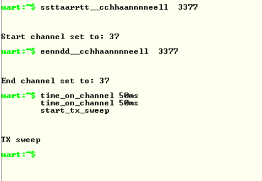
But I'm not seeing any output power on my power meter which is also set in 2402mHz frequency.
Regards,
Arun
Hi
It looks to me like there is a few things here:
- You are running a sweep over a single channel, I would rather use the constant carrier wave as you would with the current config only stay at channel 37 for 50ms
- You power meter is set to what would be channel 2 while you are sending at channel 37
- I can't see that you have adjusted the output power
- Your test setup is still a mystery to me.
Regards
Runar
Hi Runar,
on one of your previous response, you've said
" Since the DK has a extra circuits outside the nrf5340 you need to have the correct setup so you don't measure the current draw of the whole DK."
what is the correct setup that I should follow to measure just the current drawn by nRF5340 on any state?
Regards,
Arun
runsiv said:I was supposed to write custom board. Since you are using the DK we have guide for current measurement here.
Regards
Runar
->I'm following this same method mentioned in the document in section "measure average current with ampere meter".
-----> You power meter is set to what would be channel 2 while you are sending at channel 37
channel 2 is frequency 2408 right? I'm the power meter to frequency 2402.
------>You are running a sweep over a single channel, I would rather use the constant carrier wave as you would with the current config only stay at channel 37 for 50ms
Can you please guide me configure the same?
---->Your test setup is still a mystery to me
I'm connecting the DK to my laptop through USB cable, flashing the "radio test" example, giving commands to the DK using Tera Term, like the log shared earlier. Connecting the external antenna(J1) to the power meter. VDD and VDD_HV points to the ammeter.
Regards,
Arun

