I have a question about UART.

Hello.

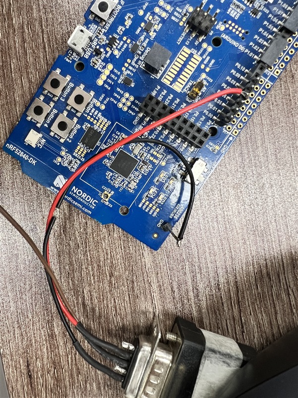
I have implemented a simple source code to transmit UART data to a PC using the nRF52840-DK board.

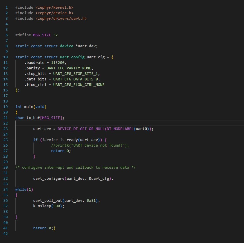
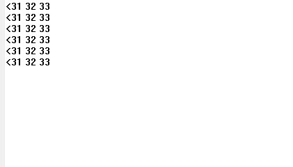
I transmitted 0x31, 0x32, 0x33, and I have confirmed that this data is received correctly on the PC.

After confirmation, I have built the project to fit the custom development board with nRF52833 connected, and downloaded the corresponding source code onto it.

ex)
1. Create a new application -> create blank app 
2. new project -> copy source
3. bulid (nRF52833 DK. set TX - 0.15, RX - 0.17)
4. download
 

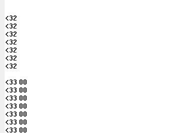
The desired results are not being received as opposed to the previous outcome.

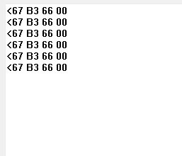
I've checked the TX, RX pin configurations as well as the baud rate, stop bit, data bit, parity, and flow control values, but it seems like the issue lies elsewhere.

Since the received values are consistently the same, it appears that the issue is not related to the baud rate.

Could you give me advice that might help me guess the cause?

plz...
Parents
  • Hi

    What pins are you using for UART on your custom board exactly P0.15 and P0.17? Are you not using flow control on the DK either? And can you confirm whether your custom board has an external 32.768kHz oscillator or not? If not you need to configure the device to use the internal RC oscillator instead. Also, how much power are you supplying this custom board with on your end?

    Best regards,

    Simon

  • Hello,

    I am currently testing on the nRF52840-DK board rather than a custom board. When communicating with the PC via jLink-CDC-UART-PORT, the data I send is received correctly.

    = send: 0x32, receive: 0x32 

    Good.

    Next, I want to test UART using a USB to serial cable, so I connected the external pins of the DK board as follows:

    P0.06 TX - Cable RX GND - GND

    After checking the received data on the PC, I found that the following data arrived:

    = send: 0x32, receive: 0x33, 0x00

    I don't understand what this difference means. Have I made a mistake in the project settings?

    Below is the test project file.

    1185.uarttest.zip

Reply
  • Hello,

    I am currently testing on the nRF52840-DK board rather than a custom board. When communicating with the PC via jLink-CDC-UART-PORT, the data I send is received correctly.

    = send: 0x32, receive: 0x32 

    Good.

    Next, I want to test UART using a USB to serial cable, so I connected the external pins of the DK board as follows:

    P0.06 TX - Cable RX GND - GND

    After checking the received data on the PC, I found that the following data arrived:

    = send: 0x32, receive: 0x33, 0x00

    I don't understand what this difference means. Have I made a mistake in the project settings?

    Below is the test project file.

    1185.uarttest.zip

Children
Related