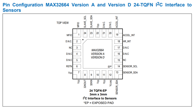
I am developing a Pulse Oximeter and I have designed my own customized PCB. The PCB has nrf52832 as micro ( MDBT42Q ), MAX32664 version A as sensor hub, MAX30101 optical module and KX122-1037 accelerometer. The PCB connections have been designed following MAXREFDES200 design: both sensors are connected to the sensor hub through SENSOR SCL/SDA, while the sensor hub is connected to the nrf52832 SoC solution via SLAVE SDA/SCL.
SLAVE SCL, SLAVE SDA, RSTN, MFIO pins of the sensor hub (MAX32664) are exposed to update the firmware versione to the latest released (the sensor hub is sold by international distributors with the factory version of its own firmware. It is therefore necessary to update this version to the latest version released). From the MAX32664 datasheet is known that it is possible to do this procedure exploiting MAX32630FTHR and MAX32625PICO. In fact, Maxim provides a firmware image for the MAX32630FTHR that turns it into an msbl programmer for the MAX32664. Basically, by loading the .bin file on the development board through the MAX32625PICO microcontroller, it is possible to transform this board into a programmer for flashing the new firmware to the sensor hub.
The steps I followed are:
• Connect the JTAG Cable from the MAX32625PICO to the MAX32630FTHR, and connect both devices to a PC with a micro-USB cable.
• Drag and drop the “MRD220 MAX32630 Host FW x˙x˙x ASCII.bin” file in the msbl flashing tools software package onto the DAPLINK drive. The LED on the MAX32625PICO started blinking as it programs the MAX32630FTHR for around 20seconds. The .bin file I used is the one found in the folder "MAXREFDES220_HR_SpO2_Win10_v4.0.0" downloaded from Analog Device WebSite.
• The pins of MAX32664 and MAX32630FTHR have been connected (P3_5 to SLAVE_SCL, P3_4 to SLAVE_SDA, P5_6 to RSTN, P5_4 to MFIO, GND to GND, 3v3 volt to VDD of the custom PCB (which through a voltage regulator brings 1.8V to the sensor hub).
• Re-connect the MAX32630FTHR to the PC (Windows)
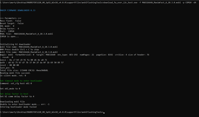
• Opened a command prompt in the directory where there are the executable (“download fw over i2c host.exe” , found in the folder "MAXREFDES220_HR_SpO2_Win10_v4.0.0" downloaded from Analog Device WebSite) and the .msbl ("MAX32664A_MaximFast_A_10.3.0" found in the "MAX32664A_HR_SpO2_v10.3.0_(1)" folder downloaded from Analog Device, searching for MAx32664 product).
The last passage gives error: "unable to enter bootloader mode, err... -1"
But when I try to enter bootloader mode by code:
nrf_gpio_cfg_output (mfioPin);
nrf_gpio_cfg_output (resetPin);
// Set the RSTN pin low for 10ms.
nrf_gpio_pin_clear(resetPin);
// While RSTN is low, set the MFIO pin to low (MFIO pin should be set low at least 1ms
// before RSTN pin is set high.)
nrf_gpio_pin_clear(mfioPin);
// After the 10ms has elapsed, set the RSTN pin high.
nrf_delay_ms(10);
nrf_gpio_pin_set(resetPin);
// After an additional 50ms has elapsed, the MAX32664 is in bootloader mode
nrf_delay_ms(50);
// Read byte 0x01 0x00 0x08
nrf_gpio_cfg_output (resetPin) ;
nrf_gpio_cfg_output (mfioPin) ;
// Set mode to 0x08 for bootloader mode 0x01 0x00 0x08
uint8_t StatusByte = WriteByte_cmd(0x01,0x00,0x08,20,mfioPin);
if( StatusByte == 0) {
nrf_gpio_pin_clear(LED);
}
// 0x02 0x00
nrf_delay_ms(1000);
uint8_t ReturnByte = readByte (0x02, 0x00);
if( ReturnByte == 0x08) {
nrf_gpio_pin_set(LED);
}
// 0xAA 0x80 0x02 0x00 0x15*
nrf_delay_ms(1000);
uint8_t s = WriteByte_cmd_16(0x80,0x02,0x00,0x15,20,mfioPin);
if( s == 0x00) {
nrf_gpio_pin_clear(LED);
}
StatusByte = WriteByte_cmd(0x01,0x00,0x00,20,mfioPin);
It properly does it.
How can I solve my problem? I need to uodate the firmware of the sensor hub.