Unable to read from GPIO P0.10 on nRF5340

I am trying to read from a GPIO configured as input and the value returned from gpio_pin_get_raw() is always 0. I have verified the voltage into the pin is 3.3v. Here is the code

#include <zephyr/kernel.h>
#include <stdio.h>
#include <string.h>
#include <stdlib.h>
#include <zephyr/device.h>
#include <zephyr/devicetree.h>
#include <zephyr/drivers/gpio.h>

#define GPIO0_NODE DT_NODELABEL(gpio0)
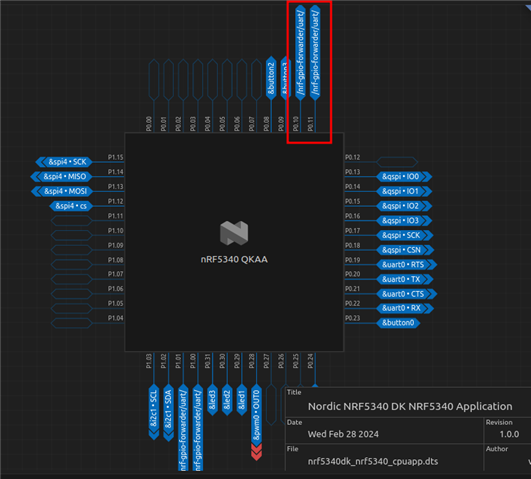
#define ROGUE_IRQ_PIN 10

const struct device *gpio0_dev;

void main(void)
{
    gpio0_dev = DEVICE_DT_GET(GPIO0_NODE);
    gpio_pin_configure(gpio0_dev, ROGUE_IRQ_PIN, GPIO_INPUT);
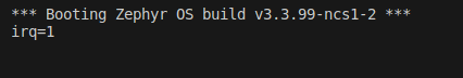
    printk("irq=%d\n", gpio_pin_get_raw(gpio0_dev, ROGUE_IRQ_PIN));
}
I'm using ncs v2.4.2
This seems very simple. Am I missing something in my configuration? I have CONFIG_GPIO=y in my prt.conf. Do I need something in my device tree overlay?


Parents
  • Hello,

    I didn't find any errors in the code you've posted. I also confirmed that it works correctly on my 5340 DK without the need for any additional overlay files.

    Project

    pin_read.zip

    Compiled .hex

    8130.zephyr.hex

    Result

    Could you please try to program the device with the zephyr.hex file above to see if that works? You can use nrfjprog to program it:

    $ nrfjprog --program zephyr.hex --chiperase --verify -r
    

    Note: P0.10 will be assigned to the network core by default if you build for the the 'nrf5340dk_nrf5340_cpuapp' board with a project that enables the network core (nordic,nrf-gpio-forwarder). 

    Best regards,

    Vidar

  • Thank you. Yes, your hex file works on my system. From analyzing your sample app the main difference is you are using an empty prj.conf file?

    We do plan to use the network processor and I had CONFIG_BT=y in my prj.conf file. Setting this to CONFIG_BT=n allows my app to also read P0.10 now.

    Is it possible to remap nrf-gpio-forwarder to use a different gpio than P0.10? What would the overlay file for that look like?

  • Yes, setting CONFIG_BT=y will enable the network core, which in turn enables the GPIO forwarding to the network core. 

    You can create an overlay to change which pins are to be forwarded in the uart group for the gpio_fwd node. As an example, this overlay will remove the HWFC pins:

    /* Remove flow control pins*/
    &gpio_fwd {
        uart {
            gpios = <&gpio1 1 0>, <&gpio1 0 0>;
        };
    };
    

    The DT for the netcore build (hci_rpmsg) should also be updated so it doesn't try to use the pins that are no longer being forwarded:

    /* remove flow control pins */
    &pinctrl {
    	uart0_default: uart0_default {
    		group1 {
    			psels = <NRF_PSEL(UART_TX, 1, 1)>;
    		};
    		group2 {
    			psels = <NRF_PSEL(UART_RX, 1, 0)>;
    			bias-pull-up;
    		};
    	};
    	uart0_sleep: uart0_sleep {
    		group1 {
    			psels = <NRF_PSEL(UART_TX, 1, 1)>,
    				<NRF_PSEL(UART_RX, 1, 0)>;
    			low-power-enable;
    		};
    	};
    };

    To apply the overlay above to the hci_rpmsg child image, you can create a folder named 'child_image' within your project's source directory and place your overlay file inside it:

    ├── child_image
    │   └── hci_rpmsg.overlay
     

    https://developer.nordicsemi.com/nRF_Connect_SDK/doc/latest/nrf/config_and_build/multi_image.html#permanent-configuration-changes-to-child-images 

Reply
  • Yes, setting CONFIG_BT=y will enable the network core, which in turn enables the GPIO forwarding to the network core. 

    You can create an overlay to change which pins are to be forwarded in the uart group for the gpio_fwd node. As an example, this overlay will remove the HWFC pins:

    /* Remove flow control pins*/
    &gpio_fwd {
        uart {
            gpios = <&gpio1 1 0>, <&gpio1 0 0>;
        };
    };
    

    The DT for the netcore build (hci_rpmsg) should also be updated so it doesn't try to use the pins that are no longer being forwarded:

    /* remove flow control pins */
    &pinctrl {
    	uart0_default: uart0_default {
    		group1 {
    			psels = <NRF_PSEL(UART_TX, 1, 1)>;
    		};
    		group2 {
    			psels = <NRF_PSEL(UART_RX, 1, 0)>;
    			bias-pull-up;
    		};
    	};
    	uart0_sleep: uart0_sleep {
    		group1 {
    			psels = <NRF_PSEL(UART_TX, 1, 1)>,
    				<NRF_PSEL(UART_RX, 1, 0)>;
    			low-power-enable;
    		};
    	};
    };

    To apply the overlay above to the hci_rpmsg child image, you can create a folder named 'child_image' within your project's source directory and place your overlay file inside it:

    ├── child_image
    │   └── hci_rpmsg.overlay
     

    https://developer.nordicsemi.com/nRF_Connect_SDK/doc/latest/nrf/config_and_build/multi_image.html#permanent-configuration-changes-to-child-images 

Children
Related