
We need to route P0.00 - P0.01 crystal clock to P0.10
Is there a way to do that?
We need to route P0.00 - P0.01 crystal clock to P0.10
Is there a way to do that?
Some more information - we are using Zephyr with nrf connect V1.9.1
Someone suggested Distributed programmable peripheral interconnect will work. Will it? if yes, how to do that in the above case?
If no, what is the process to do it. We actually need 32.768Khz freq to be utilized from external oscillator than the one given by MAXIM AFE (MAX86178) as it creates more noise than the external oscillator. We are trying to get clean ECG signals.

Not quite clear what you are looking for; it's easy to get 32.768kHz/2 (ie crystal divided by 2) routed from the P0.00/P0.01 32.768kHz crystal to an output on P0.10, but that's only 16.384kHz. For clean high-accuracy ECG you could try the Mems oscillators, lots to choose from with power required varying from few hundred nA to few mA but something like this: sit1532
If using an external 32.768kHz Mems for the ECG AFE then it would make sense to chuck away the crystal and feed the MEMS into P0.00 instead and selecting external-driven oscillator mode (as well as P0.10 if needed, though that seems superfluous in this case). The ECG AFEs usually require a higher frequency then 32kHz, so the actual requirement is a little unclear here.

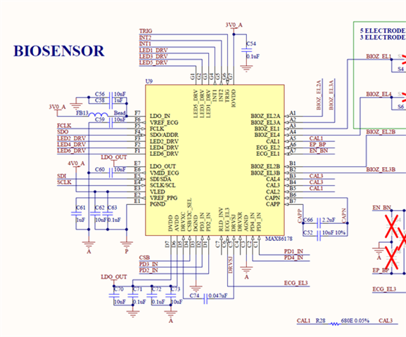
Hi, Thanks for the response. MAX86178 needs 32.768Khz for ECG signals. We forgot to add the crystal as shown in this original schematicsMAXREF_106_SCH-4 (1).pdfSIT1572AI-J3-18E-DCC-32.768
However we have one oscillator at P0.00 - P0.01
We were thinking if we could use that for the purpose and the the signals. Although there is an internal oscillator inside MAX86178, but using that induces a lot of noise.
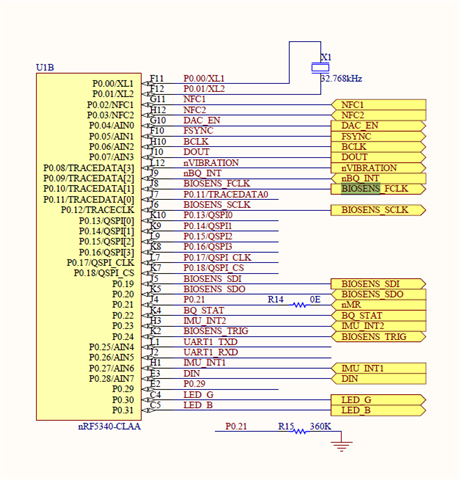
Our schematics below:
has the F5 (FCLK) connected to P0.10 pin of nrf5340 instead to the external oscillator.
We hope we could explain the thing.
Regards
Vivek
Ah, I don't have access to the MAX86178 datasheet (requires NDA).
Two options:
1) see if the datasheet allows operation of the AFE from 16.384kHz input clock on F5 FCLK, if so easy fix I can share code.
2) Try connecting P0.00 to P0.10, naughty but it will (might) probably work well enough for trials. P0.00 is a weak "output" at 32.768kHz exciting the crystal, P0.10 in this case would have to be left as a floating input.
Edit: Option 3 use a PWM to generate a clock close to 32.768kHz; downside is power consumption since to get good PWM timing accuracy the 32MHz crystal has to be enabled
Hi,
Thanks for the response. Please share the code for option 1 and let us see the result.
Regards
Vivek
I don't have a tested DPPI option to hand for the nRF5340; here is a tested PPI example for the nRF52832/nRF52840 with a guess at a working nRF5340 DPPI:
#define FCLK_PIN 10  // P0.10
void TestFCLK(void)
{
   // Output the 32.768kHz crystal using h/w toggle on FCLK_PIN - will show as 16.384kHz
   nrf_gpio_cfg_output(FCLK_PIN);
   // Select 32kHz clock source
   NRF_CLOCK->LFCLKSRC = CLOCK_LFCLKSRC_SRC_Xtal << CLOCK_LFCLKSRC_SRC_Pos;
   // Start 32.768kHz clock
   NRF_CLOCK->EVENTS_LFCLKSTARTED = 0;
   NRF_CLOCK->TASKS_LFCLKSTART = 1;
   while (NRF_CLOCK->EVENTS_LFCLKSTARTED == 0) ;
   // Clear started event otherwise won't sleep
   NRF_CLOCK->EVENTS_LFCLKSTARTED = 0;
   // Start RTC, enable TICK event
   NRF_RTC0->EVTENSET = RTC_EVTENSET_TICK_Msk;
   NRF_RTC0->TASKS_START = 1;
   // Configure GPIOTE to control output pin
   NRF_GPIOTE->CONFIG[0] = GPIOTE_CONFIG_MODE_Task << GPIOTE_CONFIG_MODE_Pos | GPIOTE_CONFIG_POLARITY_Toggle << GPIOTE_CONFIG_POLARITY_Pos | FCLK_PIN << GPIOTE_CONFIG_PSEL_Pos;
#if 1 // nRF52832
   // Connect TICK event of the RTC to the output pin using PPI and GPIOTE, toggle so 32768/2=16384Hz expected
   NRF_PPI->CH[0].EEP = (uint32_t)&NRF_RTC0->EVENTS_TICK;
   NRF_PPI->CH[0].TEP = (uint32_t)&NRF_GPIOTE->TASKS_OUT[0];
   NRF_PPI->CHEN = PPI_CHEN_CH0_Msk;
#else // nRF5340 - not tested
   // Connect TICK event of the RTC to the output pin using DPPI and GPIOTE, toggle so 32768/2=16384Hz expected
   NRF_RTC0->PUBLISH_TICK       = (DPPI_PUB_CHIDX_Ch0) | (DPPI_PUB_EN_Msk);
   NRF_GPIOTE->SUBSCRIBE_OUT[0] = (DPPI_SUB_CHIDX_Ch0) | (DPPI_SUB_EN_Msk);
   NRF_DPPIC->CHENSET           = (DPPI_CHENSET_CH0_Set << DPPI_CHENSET_CH0_Pos);
#endif
}
Edit: This using-the-dppi-on-the-nrf5340-gpio-toggling might be a useful guide