COM port forwarding on nRF9160-DK / Pin conflict with nRF7002-EK

Hello, we are using the nRF9160-DK for one of our project demonstrators (proof of concept, prototype).

For easier implementation, we will not use the nRF52840 MCU, so no logic for individually switching of the COM ports is implemented.

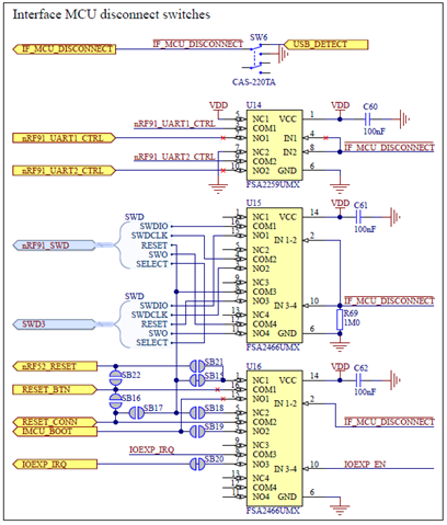
As I need more I/O pins for our interface devices, I am trying to disable some of the the COM forwarding pins. I don't need flow control, but there is no switch to disable the RTC/CTS pins like on the nRF5340-DK. Further, I was searching for an easy way to disable only one of the COM ports (all four pins). But then I realized this extremely strange circuit:

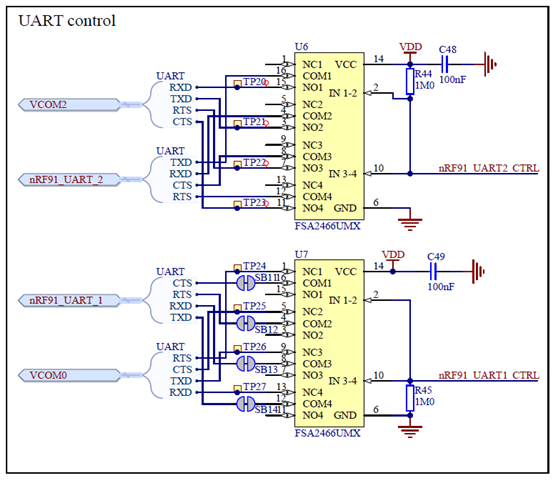
Do I understand correctly that the Enable signal for nRF91_UART2 (upper ic) is pulled to High while the signals are connected on the "Normally Open" pins (which are active when Enable = High), whereas the Enable signal for nRF91_UART1 (lower ic) is pulled to Low while the signals are connected on the "Normally Close" pins (which are active when Enable = Low)?

This means both ports are pre-enabled while in one case with a High signal, in the other case with a Low signal? Does this make any sense ????

And does this mean that I can only either enable both or disable both with SW6, unless I use the control signals from the nRF52840? It would be nice to have one UART connection for the debug console

My point is, I want to use toe nRF7002-EK which has the IOVDD_EN and BUCK_EN signals on the same pins as UART2_RXD and UART2_TXD. And I do not want to cause a short-cut on any of the devices when the interface MCU uses these signals as UART while the nRF9160 and the nRF7002-EK as control signals for the power switches.

Any suggestions?

Best regards,

Michael

  • Hello,

    Let me check if one of the designers of the nRF9160-DK can comment.

    Kenneth

  • This means both ports are pre-enabled while in one case with a High signal, in the other case with a Low signal? Does this make any sense ????

    Yes, you are correct, one is active high and one is active low, I agree this is unfortunate. If some backround is of interest, early on it was planned to pipe all data through one UART, and thus only have 1 UART enabled by default. Since the switch IC uses less current with the input signal low it made sence to have the default setting with low input signal. When it later was decided that both UARTs had to be enabled by default there were already a lot of kits with this configuration made so changing the polarity was considered to make more "noise". The polarity would then have been dependent on the kit version which is absolutely not desirable.

    And does this mean that I can only either enable both or disable both with SW6, unless I use the control signals from the nRF52840? It would be nice to have one UART connection for the debug console

    SW6 does not control UART switches directly. The "IF_MCU_DISCONNECT", coming from SW6, is an input to nRF52840, so if SW6 diasbles the UARTs or not is dependent on the FW running in nRF52840.

    Hope that helps,
    Kenneth

  • Hi Kenneth,

    thank you for telling me about the background of this circuit!

    SW6 does not control UART switches directly. The "IF_MCU_DISCONNECT", coming from SW6, is an input to nRF52840, so if SW6 diasbles the UARTs or not is dependent on the FW running in nRF52840.

    Here I disagree, please have a look at this part of the schematic (and the "UART control" block posted last time):

    If /IF_MCU_DISCONNECT is pulled to GND via SW6, U14 connects nRF91_UART1_CTRL to VDD and nRF91_UART2_CTRL to GND. This directly disconects the VCOM* ports from the nRF91. The nRF52 might still get a feedback signal about the switch position, but it does not control the relevant nRF91_UART*_CTRL signals at the switches anymore.

    Unfortunately, looking into the schematic again, I noticed that /IF_MCU_DISCONNECT also disables the power supply to the IMCU:

    If I understand correctly, this means that I cannot disable the VCOM ports with SW6 and still use the develompent kit's built in debugger. I either have to use a separate debugger or configure the nRF52 to disable the VCOM port in question.

    This leads me back to my initial question: How can I use the nRF7002-EK safely on the nRF9160-DK? Please have a look at Arduino header P3.1-P3.2, which is nRF9160 port P0.0 and P0.1. These pins are connected to UART2 RXD and TXD (connected to VCOM2). The nRF7002-EK uses the same Arduino pins P3.1-P3-2 for IOVDD_EN and BUCK_EN.

    Is my assumption correct that there are only two ways to safely use the nRF7002-EK on the nRF9160-DK?

    (1) Do not use the onboard debugger - turn it off via SW6 or use a different power source (e.g. VIN3-5V on P20) - and program the nRF91 via the nRF91 Debug In connector P18

    (2) First program the nRF52 before you mount the nRF7002-EK so that it pulls nRF91_UART2_CTRL to Low, which disconnects the VCOM2 from the nRF91 and frees the Arduino pins P3.1&P3.2

    If something slipped my mind, please let me know.

    Best regards,

    Michael

  • puz_md said:
    If /IF_MCU_DISCONNECT is pulled to GND via SW6, U14 connects nRF91_UART1_CTRL to VDD and nRF91_UART2_CTRL to GND. This directly disconects the VCOM* ports from the nRF91. The nRF52 might still get a feedback signal about the switch position, but it does not control the relevant nRF91_UART*_CTRL signals at the switches anymore.

    Sorry, You are correct, I overlooked this switch.

    puz_md said:
    If I understand correctly, this means that I cannot disable the VCOM ports with SW6 and still use the develompent kit's built in debugger. I either have to use a separate debugger or configure the nRF52 to disable the VCOM port in question.

    Correct, SW6 is meant to disconnect the debugger from the circuit entirely. To only disable parts, this must be done in the nRF52840 board controller.

    puz_md said:

    (1) Do not use the onboard debugger - turn it off via SW6 or use a different power source (e.g. VIN3-5V on P20) - and program the nRF91 via the nRF91 Debug In connector P18

    (2) First program the nRF52 before you mount the nRF7002-EK so that it pulls nRF91_UART2_CTRL to Low, which disconnects the VCOM2 from the nRF91 and frees the Arduino pins P3.1&P3.2

    This looks correct, however in (1) you can still use USB to supply the kit if that is desired. 

    There is an overlay which will disable the UART on this pins when using nRF7002EK. See sdk-nrf-2.5.2\samples\cellular\lwm2m_client\boards\nrf9160dk_with_nrf7002ek.overlay

    Kenneth

Related