nRF Connect SDK implement i2c mux

I'm going to build an project with 2 AS5600 sensors, and also using I2C mux(TCA9548A) to communicate with 2 sensors.

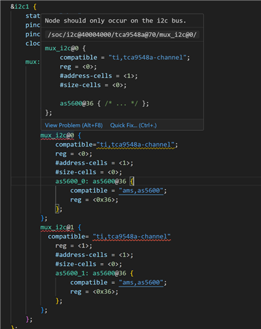
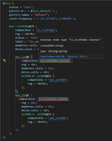
I have some problem with devicetree. There are two errors in &i2c1 node,  how could I fix this?

Also, when I try to build the project, I got an error message:

error: static assertion failed: "I2C multiplexer channels must be initialized after their root"

Please give me some advices.

I had already read this https://devzone.nordicsemi.com/f/nordic-q-a/100595/problem-configuring-twi-i2c-interface, but nothing help

This is my .dts file currently:

// Copyright (c) 2024 Nordic Semiconductor ASA
// SPDX-License-Identifier: Apache-2.0

/dts-v1/;
#include <nordic/nrf52832_qfaa.dtsi>
#include "custom_nrf52832-pinctrl.dtsi"

/ {
	model = "custom_nrf52832";
	compatible = "myself,custom-nrf52832";

	chosen {
		zephyr,sram = &sram0;
		zephyr,flash = &flash0;
		zephyr,code-partition = &slot0_partition;
		zephyr,console = &uart0;
		zephyr,shell-uart = &uart0;
		zephyr,uart-mcumgr = &uart0;
	};

	leds {
		compatible = "gpio-leds";
		ledR: led_0 {
			gpios = <&gpio0 3 (GPIO_ACTIVE_LOW)>;
			label = "Red led R";
		};
		ledB: led_1 {
			gpios = <&gpio0 4 (GPIO_ACTIVE_LOW)>;
			label = "Blue led B";
		};
		// ledB: led_2 {
		// 	gpios = <&gpio0 5 (GPIO_ACTIVE_LOW)>;
		// 	label = "Blue led B";
		// };
	};

	buttons {
		compatible = "gpio-keys";
		button0: button_0 {
			gpios = <&gpio0 27 0>;
			label = "Push button switch 0";
		};

		Gsensor_INT1: INT1 {
			gpios = <&gpio0 19 0>;
			label = "Gsensor_INT1";
		};

		Gsensor_INT2: INT2 {
			gpios = <&gpio0 20 0>;
			label = "Gsensor_INT2";
		};
	};


	zephyr,user {
		io-channels = <&adc 4>;
		status = "okay";
	};
	
	vbatt {
		compatible = "voltage-divider";
		io-channels = <&adc 0>;
		output-ohms = <10000000>;
		full-ohms = <(10000000 + 10000000)>;
		// power-gpios = <&sx1509b 4 0>;
		status = "okay";
	 };

	/* These aliases are provided for compatibility with samples */
	aliases {
		led0 = &ledR;
		led1 = &ledB;
		// led2 = &ledB;
		// pwm-led0 = &pwm_ledR;
		// pwm-led1 = &pwm_ledG;
		// pwm-led2 = &pwm_ledB;
		sw0 = &button0;
		int1 = &Gsensor_INT1;
		int2 = &Gsensor_INT2;
		bootloader-led0 = &ledR;
		mcuboot-button0 = &button0;
		mcuboot-led0 = &ledR;
		watchdog0 = &wdt0;
	};
};

&flash0 {
	partitions {
		compatible = "fixed-partitions";
		#address-cells = <1>;
		#size-cells = <1>;

		boot_partition: partition@0 {
			label = "mcuboot";
			reg = <0x0 0xc000>;
		};
		slot0_partition: partition@c000 {
			label = "image-0";
			reg = <0xc000 0x32000>;
		};
		slot1_partition: partition@3e000 {
			label = "image-1";
			reg = <0x3e000 0x32000>;
		};
		scratch_partition: partition@70000 {
			label = "image-scratch";
			reg = <0x70000 0xa000>;
		};
		storage_partition: partition@7a000 {
			label = "storage";
			reg = <0x7a000 0x6000>;
		};
	};
};


&gpio0 {
	status = "okay";
};

&gpiote {
	status = "okay";
};

&uart0 {
	status = "okay";
	current-speed = <115200>;
	pinctrl-0 = <&uart0_default>;
	pinctrl-1 = <&uart0_sleep>;
	pinctrl-names = "default", "sleep";
};

&i2c0 {
	compatible = "nordic,nrf-twim";
	status = "okay";
	clock-frequency = <I2C_BITRATE_STANDARD>;
	pinctrl-0 = <&i2c0_default>;
	pinctrl-1 = <&i2c0_sleep>;
	pinctrl-names = "default", "sleep";
	label = "I2C_0";
	lsm6dsl: lsm6dsl@6a {
		compatible = "st,lsm6dsl";
		reg = <0x6a>;
		// irq-gpios = <&gpio0 19 GPIO_ACTIVE_HIGH>, 
		// 			<&gpio0 20 GPIO_ACTIVE_HIGH>;
		label = "GSENSOR";
		status = "okay";
	};
};

&i2c1 {
    status = "okay";
    pinctrl-0 = < &i2c1_default > ;
    pinctrl-names = "default";
    clock-frequency = < I2C_BITRATE_STANDARD >;
    
    mux: tca9548a@70 {
		compatible = "ti,tca9548a";
		reg = <0x70>;
		status = "okay";
		label = "i2c_mux";
		#address-cells = <1>;
		#size-cells = <0>;
		
		mux_i2c@0 {
			compatible= "ti,tca9548a-channel"
			reg = <0>;
			#address-cells = <1>;
			#size-cells = <0>;
			as5600_0: as5600@36 {
				compatible = "ams,as5600";
				reg = <0x36>;
			};
		};
		mux_i2c@1 {
		  compatible= "ti,tca9548a-channel"
			reg = <1>;
			#address-cells = <1>;
			#size-cells = <0>;
			as5600_1: as5600@36 {
				compatible = "ams,as5600";
				reg = <0x36>;
			};
		};
	};
};


&adc {
	status = "okay";
	#address-cells = <1>;
	#size-cells = <0>;

	channel@0 {
		reg = <0>;
		zephyr,gain = "ADC_GAIN_1_4";
		zephyr,reference = "ADC_REF_INTERNAL";
		zephyr,acquisition-time = <ADC_ACQ_TIME_DEFAULT>;
		zephyr,input-positive = <NRF_SAADC_AIN0>; /* P0.02 */
		zephyr,resolution = <12>;
	};

	channel@4 {
		reg = <4>;
		zephyr,gain = "ADC_GAIN_1_4";
		zephyr,reference = "ADC_REF_INTERNAL";
		zephyr,acquisition-time = <ADC_ACQ_TIME_DEFAULT>;
		zephyr,input-positive = <NRF_SAADC_AIN4>; /* P0.028 */
		zephyr,resolution = <12>;
	};
};

And the pinctrl file:

/*
 * Copyright (c) 2022 Nordic Semiconductor
 * SPDX-License-Identifier: Apache-2.0
 */

 &pinctrl {
	uart0_default: uart0_default {
		group1 {
			psels = <NRF_PSEL(UART_TX, 0, 6)>,
				<NRF_PSEL(UART_RX, 0, 8)>,
				<NRF_PSEL(UART_RTS, 0, 9)>,
				<NRF_PSEL(UART_CTS, 0, 7)>;
		};
	};

	uart0_sleep: uart0_sleep {
		group1 {
			psels = <NRF_PSEL(UART_TX, 0, 6)>,
				<NRF_PSEL(UART_RX, 0, 8)>,
				<NRF_PSEL(UART_RTS, 0, 9)>,
				<NRF_PSEL(UART_CTS, 0, 7)>;
			low-power-enable;
		};
	};

	i2c0_default: i2c0_default {
		group1 {
			psels = <NRF_PSEL(TWIM_SDA, 0, 11)>,
					<NRF_PSEL(TWIM_SCL, 0, 12)>;
			// bias-pull-up;
		};
	};

	i2c0_sleep: i2c0_sleep {
		group1 {
			psels = <NRF_PSEL(TWIM_SDA, 0, 11)>,
					<NRF_PSEL(TWIM_SCL, 0, 12)>;
			low-power-enable;
		};
	};

	i2c1_default: i2c1_default {
		group1 {
			psels = <NRF_PSEL(TWIM_SDA, 0, 14)>,
					<NRF_PSEL(TWIM_SCL, 0, 13)>;
			// bias-pull-up;
		};
	};

	i2c1_sleep: i2c1_sleep {
		group1 {
			psels = <NRF_PSEL(TWIM_SDA, 0, 14)>,
					<NRF_PSEL(TWIM_SCL, 0, 13)>;
			low-power-enable;
		};
	};

};

Here are the errors show on vscode:

Parents Reply Children
  • Hello, I was away over the weekend. Did you encounter the same error message? Please upload your screenshot or related files, and I'll try to assist you with your issue.

  • Hello, yes I had the same exact problems with the devicetree where the child node of the TCA9548A was throwing unrecognized errors and I could not interface my sensors. I still couldn't figure out the device tree no matter what I tried so I disregarded it entirely and I interfaced the TCA9548A the programmatic way by writing my own driver for it, and referenced the mux i2c0 bus directly. I used i2c_write_read() instead of i2c_write_read_dt() so the implementation is more akin to hardware definitions in other SDKs. Thanks for your reply!

  • Hi,

    What devices you are using after TCA9548A? As I know, if you correctly build your devicetree, you can interface with the device after I2C Mux directly.

    Here's part of my devicetree

    &i2c1 {
    	status = "okay";
        pinctrl-0 = <&i2c1_default>;
    	pinctrl-1 = <&i2c1_sleep>;
    	pinctrl-names = "default", "sleep";
    	label = "I2C_1";
    	mux: tca9548a@70 {
    		compatible = "ti,tca9548a";
    		reg = <0x70>;
    		status = "okay";
    		#address-cells = <1>;
    		#size-cells = <0>;
    
            ch0: mux_i2c@0 {
                compatible = "ti,tca9548a-channel";
                label = "i2c1_mux_0";
                reg = <0x0>;
                status = "okay";
                #address-cells = <0x1>;
                #size-cells = <0x0>;
    
                as5600_0: as5600@36 {
                    compatible = "ams,as5600";
                    reg = <0x36 >;
                    label = "AS5600_0";
                    status = "okay";
                };
            };
    
            ch1: mux_i2c@1 {
                compatible = "ti,tca9548a-channel";
                label = "i2c1_mux_1";
                reg = <0x1>;
                status = "okay";
                #address-cells = <0x1>;
                #size-cells = <0x0>;
    
                as5600_1: as5600@36 {
                    compatible = "ams,as5600";
                    reg = <0x36 >;
                    label = "AS5600_1";
                    status = "okay";
                };
            };
    	};
    };

    And I could access my AS5600 sensor with following code

    K_SEM_DEFINE(as5600_init_ok, 0, 1);
    
    #define AS5600_NODE_0 DT_NODELABEL(as5600_0)
    
    static const struct i2c_dt_spec dev_as5600_0 = I2C_DT_SPEC_GET(AS5600_NODE_0);
    
    uint8_t as5600_0_interface_iic_init(void)
    {
        if (!device_is_ready(dev_as5600_0.bus))
        {
            printk("I2C bus %s is not ready!\n\r", dev_as5600_0.bus->name);
            return 1;
        }
    
        return 0;
    }
    
    uint8_t as5600_0_interface_iic_deinit(void)
    {
    
        return 0;
    }
    
    uint8_t as5600_0_interface_iic_read(uint8_t addr, uint8_t reg, uint8_t *buf, uint16_t len)
    {
        int ret;
        ret = i2c_burst_read_dt(&dev_as5600_0, reg, buf, len);
        if (ret != 0)
        {
            printk("Failed to read to I2C device address 0x%c at Reg. 0x%c\n", dev_as5600_0.addr, reg);
            return 1;
        }
        return 0;
    }
    
    uint8_t as5600_0_interface_iic_write(uint8_t addr, uint8_t reg, uint8_t *buf, uint16_t len)
    {
        int ret;
        char buff1[] = {reg, buf};
        ret = i2c_write_dt(&dev_as5600_0, buff1, sizeof(buff1));
        if (ret != 0)
        {
            printk("Failed to write to I2C device address 0x%c at Reg. 0x%c\n", dev_as5600_0.addr, reg);
            return 1;
        }
        return 0;
    }
    
    void as5600_interface_delay_ms(uint32_t ms)
    {
        k_msleep(ms);
    }
    
    void as5600_interface_debug_print(const char *const fmt, ...)
    {
        va_list args;
        va_start(args, fmt);
        vprintk(fmt, args);
        va_end(args);
    }
    
    static as5600_handle_t gs_handle_ch0; /**< as5600 handle */
    
    uint8_t as5600_ch0_init(void)
    {
        uint8_t res;
    
        /* link interface function */
        DRIVER_AS5600_LINK_INIT(&gs_handle_ch0, as5600_handle_t);
        DRIVER_AS5600_LINK_IIC_INIT(&gs_handle_ch0, as5600_0_interface_iic_init);
        DRIVER_AS5600_LINK_IIC_DEINIT(&gs_handle_ch0, as5600_0_interface_iic_deinit);
        DRIVER_AS5600_LINK_IIC_READ(&gs_handle_ch0, as5600_0_interface_iic_read);
        DRIVER_AS5600_LINK_IIC_WRITE(&gs_handle_ch0, as5600_0_interface_iic_write);
        DRIVER_AS5600_LINK_DELAY_MS(&gs_handle_ch0, as5600_interface_delay_ms);
        DRIVER_AS5600_LINK_DEBUG_PRINT(&gs_handle_ch0, as5600_interface_debug_print);
    
        /* as5600 init */
        res = as5600_init(&gs_handle_ch0);
        if (res != 0)
        {
            as5600_interface_debug_print("as5600_ch0: init failed.\n");
    
            return 1;
        }
    
        return 0;
    }
    
    uint8_t as5600_ch0_read(float *angle)
    {
        uint8_t res;
        uint16_t angle_raw;
    
        /* read data */
        res = as5600_read(&gs_handle_ch0, &angle_raw, angle);
        if (res != 0)
        {
            as5600_interface_debug_print("as5600_ch0: read failed.\n");
    
            return 1;
        }
    
        return 0;
    }
    
    uint8_t as5600_ch0_deinit(void)
    {
        /* close as5600 */
        if (as5600_deinit(&gs_handle_ch0) != 0)
        {
            return 1;
        }
        else
        {
            return 0;
        }
    }

    Please have a look if this could help you.

Related