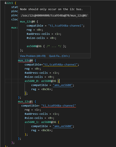
I'm going to build an project with 2 AS5600 sensors, and also using I2C mux(TCA9548A) to communicate with 2 sensors.
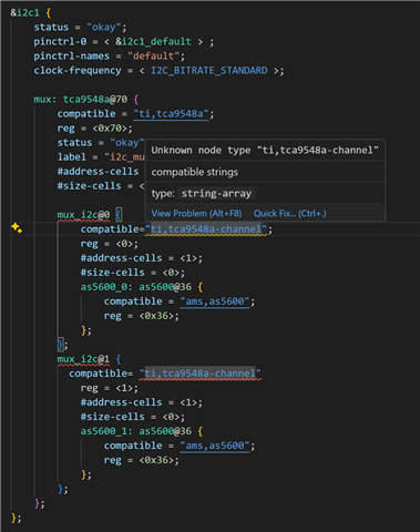
I have some problem with devicetree. There are two errors in &i2c1 node, how could I fix this?
Also, when I try to build the project, I got an error message:
error: static assertion failed: "I2C multiplexer channels must be initialized after their root"
Please give me some advices.
I had already read this https://devzone.nordicsemi.com/f/nordic-q-a/100595/problem-configuring-twi-i2c-interface, but nothing help
This is my .dts file currently:
// Copyright (c) 2024 Nordic Semiconductor ASA
// SPDX-License-Identifier: Apache-2.0

/dts-v1/;
#include <nordic/nrf52832_qfaa.dtsi>
#include "custom_nrf52832-pinctrl.dtsi"

/ {
	model = "custom_nrf52832";
	compatible = "myself,custom-nrf52832";

	chosen {
		zephyr,sram = &sram0;
		zephyr,flash = &flash0;
		zephyr,code-partition = &slot0_partition;
		zephyr,console = &uart0;
		zephyr,shell-uart = &uart0;
		zephyr,uart-mcumgr = &uart0;
	};

	leds {
		compatible = "gpio-leds";
		ledR: led_0 {
			gpios = <&gpio0 3 (GPIO_ACTIVE_LOW)>;
			label = "Red led R";
		};
		ledB: led_1 {
			gpios = <&gpio0 4 (GPIO_ACTIVE_LOW)>;
			label = "Blue led B";
		};
		// ledB: led_2 {
		// 	gpios = <&gpio0 5 (GPIO_ACTIVE_LOW)>;
		// 	label = "Blue led B";
		// };
	};

	buttons {
		compatible = "gpio-keys";
		button0: button_0 {
			gpios = <&gpio0 27 0>;
			label = "Push button switch 0";
		};

		Gsensor_INT1: INT1 {
			gpios = <&gpio0 19 0>;
			label = "Gsensor_INT1";
		};

		Gsensor_INT2: INT2 {
			gpios = <&gpio0 20 0>;
			label = "Gsensor_INT2";
		};
	};


	zephyr,user {
		io-channels = <&adc 4>;
		status = "okay";
	};

	vbatt {
		compatible = "voltage-divider";
		io-channels = <&adc 0>;
		output-ohms = <10000000>;
		full-ohms = <(10000000 + 10000000)>;
		// power-gpios = <&sx1509b 4 0>;
		status = "okay";
	 };

	/* These aliases are provided for compatibility with samples */
	aliases {
		led0 = &ledR;
		led1 = &ledB;
		// led2 = &ledB;
		// pwm-led0 = &pwm_ledR;
		// pwm-led1 = &pwm_ledG;
		// pwm-led2 = &pwm_ledB;
		sw0 = &button0;
		int1 = &Gsensor_INT1;
		int2 = &Gsensor_INT2;
		bootloader-led0 = &ledR;
		mcuboot-button0 = &button0;
		mcuboot-led0 = &ledR;
		watchdog0 = &wdt0;
	};
};

&flash0 {
	partitions {
		compatible = "fixed-partitions";
		#address-cells = <1>;
		#size-cells = <1>;

		boot_partition: partition@0 {
			label = "mcuboot";
			reg = <0x0 0xc000>;
		};
		slot0_partition: partition@c000 {
			label = "image-0";
			reg = <0xc000 0x32000>;
		};
		slot1_partition: partition@3e000 {
			label = "image-1";
			reg = <0x3e000 0x32000>;
		};
		scratch_partition: partition@70000 {
			label = "image-scratch";
			reg = <0x70000 0xa000>;
		};
		storage_partition: partition@7a000 {
			label = "storage";
			reg = <0x7a000 0x6000>;
		};
	};
};


&gpio0 {
	status = "okay";
};

&gpiote {
	status = "okay";
};

&uart0 {
	status = "okay";
	current-speed = <115200>;
	pinctrl-0 = <&uart0_default>;
	pinctrl-1 = <&uart0_sleep>;
	pinctrl-names = "default", "sleep";
};

&i2c0 {
	compatible = "nordic,nrf-twim";
	status = "okay";
	clock-frequency = <I2C_BITRATE_STANDARD>;
	pinctrl-0 = <&i2c0_default>;
	pinctrl-1 = <&i2c0_sleep>;
	pinctrl-names = "default", "sleep";
	label = "I2C_0";
	lsm6dsl: lsm6dsl@6a {
		compatible = "st,lsm6dsl";
		reg = <0x6a>;
		// irq-gpios = <&gpio0 19 GPIO_ACTIVE_HIGH>,
		// 			<&gpio0 20 GPIO_ACTIVE_HIGH>;
		label = "GSENSOR";
		status = "okay";
	};
};

&i2c1 {
    status = "okay";
    pinctrl-0 = < &i2c1_default > ;
    pinctrl-names = "default";
    clock-frequency = < I2C_BITRATE_STANDARD >;

    mux: tca9548a@70 {
		compatible = "ti,tca9548a";
		reg = <0x70>;
		status = "okay";
		label = "i2c_mux";
		#address-cells = <1>;
		#size-cells = <0>;

		mux_i2c@0 {
			compatible= "ti,tca9548a-channel"
			reg = <0>;
			#address-cells = <1>;
			#size-cells = <0>;
			as5600_0: as5600@36 {
				compatible = "ams,as5600";
				reg = <0x36>;
			};
		};
		mux_i2c@1 {
		  compatible= "ti,tca9548a-channel"
			reg = <1>;
			#address-cells = <1>;
			#size-cells = <0>;
			as5600_1: as5600@36 {
				compatible = "ams,as5600";
				reg = <0x36>;
			};
		};
	};
};


&adc {
	status = "okay";
	#address-cells = <1>;
	#size-cells = <0>;

	channel@0 {
		reg = <0>;
		zephyr,gain = "ADC_GAIN_1_4";
		zephyr,reference = "ADC_REF_INTERNAL";
		zephyr,acquisition-time = <ADC_ACQ_TIME_DEFAULT>;
		zephyr,input-positive = <NRF_SAADC_AIN0>; /* P0.02 */
		zephyr,resolution = <12>;
	};

	channel@4 {
		reg = <4>;
		zephyr,gain = "ADC_GAIN_1_4";
		zephyr,reference = "ADC_REF_INTERNAL";
		zephyr,acquisition-time = <ADC_ACQ_TIME_DEFAULT>;
		zephyr,input-positive = <NRF_SAADC_AIN4>; /* P0.028 */
		zephyr,resolution = <12>;
	};
};
And the pinctrl file:
/*
 * Copyright (c) 2022 Nordic Semiconductor
 * SPDX-License-Identifier: Apache-2.0
 */

 &pinctrl {
	uart0_default: uart0_default {
		group1 {
			psels = <NRF_PSEL(UART_TX, 0, 6)>,
				<NRF_PSEL(UART_RX, 0, 8)>,
				<NRF_PSEL(UART_RTS, 0, 9)>,
				<NRF_PSEL(UART_CTS, 0, 7)>;
		};
	};

	uart0_sleep: uart0_sleep {
		group1 {
			psels = <NRF_PSEL(UART_TX, 0, 6)>,
				<NRF_PSEL(UART_RX, 0, 8)>,
				<NRF_PSEL(UART_RTS, 0, 9)>,
				<NRF_PSEL(UART_CTS, 0, 7)>;
			low-power-enable;
		};
	};

	i2c0_default: i2c0_default {
		group1 {
			psels = <NRF_PSEL(TWIM_SDA, 0, 11)>,
					<NRF_PSEL(TWIM_SCL, 0, 12)>;
			// bias-pull-up;
		};
	};

	i2c0_sleep: i2c0_sleep {
		group1 {
			psels = <NRF_PSEL(TWIM_SDA, 0, 11)>,
					<NRF_PSEL(TWIM_SCL, 0, 12)>;
			low-power-enable;
		};
	};

	i2c1_default: i2c1_default {
		group1 {
			psels = <NRF_PSEL(TWIM_SDA, 0, 14)>,
					<NRF_PSEL(TWIM_SCL, 0, 13)>;
			// bias-pull-up;
		};
	};

	i2c1_sleep: i2c1_sleep {
		group1 {
			psels = <NRF_PSEL(TWIM_SDA, 0, 14)>,
					<NRF_PSEL(TWIM_SCL, 0, 13)>;
			low-power-enable;
		};
	};

};
Here are the errors show on vscode: