
Good Day.
I use nRF52840 + nRF21540 on my custom board. The FEM is controlled by GPIO+SPI and by default the Tx gain is set to +10 dBm (if I understand correctly). Connection to the board is done with a smartphone, which is located one meter away from the board.
1. I would like to ask you if my board is displaying the correct output power and RSSI level readings?
Program code responsible for these parameters:
void rssi_thread(void)
{
	int8_t txp;
	int8_t txp_get = 0;
	int8_t rssi = 0xFF;

	while(1){

		if (!default_conn){
			k_msleep(1000);
		}
		else{
			get_tx_power(BT_HCI_VS_LL_HANDLE_TYPE_CONN, default_conn_handle, &txp);
			LOG_INF("TxP = %d\n", txp);

			get_tx_power(BT_HCI_VS_LL_HANDLE_TYPE_ADV, 0, &txp_get);
			LOG_INF("TxP_GET = %d\n", txp_get);

			read_conn_rssi(default_conn_handle, &rssi);
			LOG_INF("RSSI level = %d\n", rssi);
		}
	k_msleep(1000);
	}
}
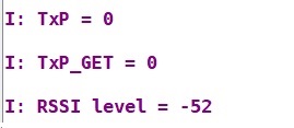
When CONFIG_BT_CTLR_TX_PWR_ANTENNA=0 is set, I see the following readings -->
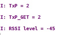
When CONFIG_BT_CTLR_TX_PWR_ANTENNA=4 is set, I see the following readings -->
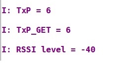
When CONFIG_BT_CTLR_TX_PWR_ANTENNA=8 is set, I see the following readings -->
When CONFIG_BT_CTLR_TX_PWR_ANTENNA=-20 (I don't know if this value can be used) is set, I see the following readings -->
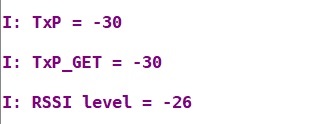
2. Why does setting the power to -20 improve the RSSI value?
3. The hci_pwr_ctrl example uses the txp and txp_get variables when displaying the Tx Power value. Is there a difference between them?
4. This TxP value does not take into account the gain from the FEM? How do I then display the transmission power taking into account the FEM?
I hope for your help with these questions.
Thank you!

