The interrupt timing of IRQ_DIRECT_CONNECT is different from expected.

Hello,

Currently, I am creating firmware that generates an IRQ_DIRECT_CONNECT interrupt at the timing when SPIM4 transfer is completed (ENDTX).

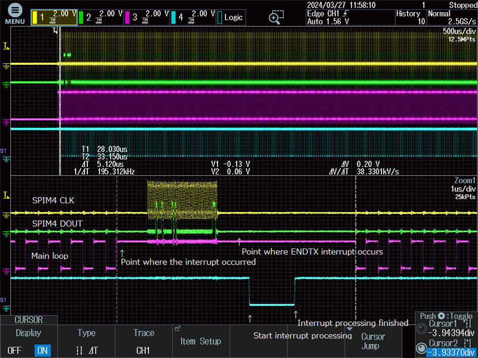
However, the interrupt timing is not at ENDTX but near the start of SPIM4 operation.

Since an interrupt occurs at the start, the current process is waiting for the ENDTX event within the interrupt. How should I set it to generate an interrupt at ENDTX?

IRQ_DIRECT_CONNECT and irq_enable settings:

IRQ_DIRECT_CONNECT(SPIM4_IRQn, 0,spim4_event_handler,IRQ_ZERO_LATENCY);
irq_enable(SPIM4_IRQn);

Interrupt handler settings:

static void spim4_event_handler(nrfx_spim_evt_t const*p_event, void *p_context)
{	
	while(NRF_SPIM4->EVENTS_ENDTX == 0){;}
	NRF_SPIM4 -> EVENTS_ENDTX = 0x00000000; 
}

Register settings before data transfer:

NRF_SPIM4 -> INTENCLR = 0x00080152;
NRF_SPIM4 -> INTENSET = 0x00000100;

Register settings after data transfer:

NRF_SPIM4 -> INTENCLR = 0x00000100;

best regard,

Parents
  • Hello,

    I think the SPIM peripheral in the nRF5340 does not directly support an ENDTx interrupt. Using a GPIO pin to monitor the state of the SPI lines (MISO or MOSI) and then configuring the GPIO pin to generate an interrupt when the line state changes such that it indicates the end of the transmission will be a solution for your use case. You can also consider using the software interrupt. Take a look at this thread, which explains this a bit briefly.

    Please expect a delay after this response. I will be responding after Tuesday next week, as it is Easter vacation here in Norway.

     Kind Regards,

    Abhijith

  • Hello,

    Thank you for your reply.

    Although the nRF5340's SPIM peripheral does not directly support ENDTx interrupts, SPIM4_IRQn was defined in the include file nrf5340_application.h.

    Currently, the ENDTx interrupt is working in the program, but is there a concrete way to trigger it with ENDTx?

    best regard,

  • Hello,


    Sorry, I didn't explain it enough.


    The program is performing the following actions:
    1.Main loop (red line) constantly switching GPIO for testing purposes.
    2.I am trying to generate an interrupt process (blue line) at SPIM4's ENDTX.
    3. GPIO is set to "0" at the beginning of interrupt processing and set to "1" at the end of interrupt processing.


    The problem with this program is that the interrupt processing starts near the start of SPIM4's operation, not at ENDTX.
    This can be confirmed by the fact that GPIO switching disappears in the Main loop.
    For this reason, we have temporarily included a process to wait for ENDTX in the interrupt process.

    Also, I set GPIO to "0" before waiting for ENDTX in the interrupt process, but I am also concerned that it starts around ENDTX.
    I think the delay from when an interrupt occurs to the start of processing is long.

    Just to confirm, is it correct for SPIM4's ENDTX interrupt processing to always start from the SPIM4's start point?

    best regard,

  • I think your analysis of the interrupt is not correct, unless I'm missing something. The ENDTX interrupt occurs at the end of the TX buffer transmission, not at the start. If padding bytes are used via ORC to match a longer Rx buffer than the Tx buffer (ie keeps the SCLK running until Rx complete) then the ENDTX interrupt occurs before the end of the full SPIM4 transaction, but not at the start as I mentioned earlier. The way to know when the interrupt is active is to drive the port pin low at the start of the interrupt and high at the end of the interrupt in the interrupt code, which is what I assume you are doing, and that shows the active portion of the SPIM4 interrupt. This means that "The point where the interrupt occurred" marked on the trace is not correct; that might be the point at which code wrote to the SPIM4 peripheral to start a transaction, but it is not the interrupt itself. So the question is how did you determine that point?

    NRF_SPIM4 -> INTENSET = 0x00000040;
    // Handle and clear all triggering events
    static void spim4_event_handler(nrfx_spim_evt_t const*p_event, void *p_context)
    {
        PortPinLow(); // Drive port pin low here
    	if(NRF_SPIM4->EVENTS_END)
    	{
    	    NRF_SPIM4->EVENTS_END = 0;
    	}
    	... other stuff in interrupt
        PortPinHigh(); // Drive port pin high here
    }

    "This can be confirmed by the fact that GPIO switching disappears in the Main loop". Something is blocking; another interrupt, a blocking wait, or something which needs identifying; it is not the SPIM4 interrupt itself.

  • The start of the transaction is automatically executed by DPPI (SPIM3 PUBLISH_ENDRX -> SPIM4 SUBSCRIBE_START), and Main loop does nothing other than repeat GPIO switching.

    Does using DPPI cause this kind of phenomenon?

  • Hard diagnosing issues with only partial information; the delayed SPIM4 interrupt may be due to the SPIM3 interrupt if that takes significant time, what does SPIM3 interrupt do? Can you post the SPIM3 code? I ask again, why do you think SPIM4 interrupt occurs at the mark on the trace? I can state unequivocally that it does not.

    DPPI does not affect timing in the way you describe.

  • I'm sorry, I thought that SPIM3 did not use interrupts, but in reality, it used interrupts unintentionally.
    By disabling SPIM3 interrupts, an interrupt will now occur at SPIM4's ENDTX.

    Thank you very much for your help.

Reply Children
No Data
Related