Xiao BLE Sense & Round Display - Zephyr+MicroSD

Hi there,

I am trying to develop a simple application that must write information within a micro SD card (nothing too fancy, it is just plain data read from the internal accelerometer sensor).

/*********************************/

First of all, let me summarize what I am using and what program I have uploaded to the device:

  • Hardware:
    • Xiao BLE Sense.
    • Round display expansion board.
    • A 16GB micro SD card.
  • Software:
    • Visual Studio Code.
    • nRF Connect for VS Code Extension Pack (latest version).
    • nRF Connect SDK Toolchain v2.5.2
    • nRF Connect SDK v2.5.2
    • Zephyr OS.

I have downloaded the FatFS example from the zephyr GitHub (including some additional new prints only), which compiles and loads to the devices without any issue... but the outcome I receive is not good at all:

Xiao output

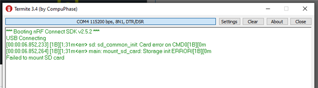
It may be something wrong in either the app.overlay or prj.conf files (or somewhere else, I do not know, I am new using the Zephyr OS).

In any case, I attach those two so as you may take a look at them:

&spi2 {
    compatible = "nordic,nrf-spim";
    status = "okay";
    cs-gpios = <&gpio0 0x1C (GPIO_ACTIVE_LOW | GPIO_PULL_UP)>;
    pinctrl-0 = <&spi2_default>;
    pinctrl-1 = <&spi2_sleep>;
    pinctrl-names = "default", "sleep";
    sdhc0: sdhc@0 {
            compatible = "zephyr,sdhc-spi-slot";
            reg = <0>;
            status = "okay";
            mmc {
                compatible = "zephyr,sdmmc-disk";
                status = "okay";
            };
            spi-max-frequency = <24000000>;//8000000 /24000000 //16000000
    };
};


&spi2_default {
    group1 {
        psels = <NRF_PSEL(SPIM_SCK, 1, 13)>,
            <NRF_PSEL(SPIM_MOSI, 1, 15)>,
            <NRF_PSEL(SPIM_MISO, 1, 14)>;
        bias-pull-up;
    };
};

&spi2_sleep {
    group1 {
        psels = <NRF_PSEL(SPIM_SCK, 1, 13)>,
            <NRF_PSEL(SPIM_MOSI, 1, 15)>,
            <NRF_PSEL(SPIM_MISO, 1, 14)>;
        bias-pull-up;
        low-power-enable;
    };
};

CONFIG_GPIO=y
CONFIG_STDOUT_CONSOLE=y
CONFIG_I2C=y
CONFIG_SPI=y
CONFIG_SENSOR=y
CONFIG_LSM6DSL_TRIGGER_GLOBAL_THREAD=y
CONFIG_CBPRINTF_FP_SUPPORT=y

CONFIG_BT=y
CONFIG_LOG=y
CONFIG_BT_SMP=y
CONFIG_BT_DEBUG_LOG=y
CONFIG_BT_MAX_CONN=1
CONFIG_BT_GATT_CLIENT=y
CONFIG_BT_L2CAP_TX_MTU=247
CONFIG_BT_L2CAP_TX_BUF_COUNT=5
CONFIG_BT_PERIPHERAL=y
CONFIG_BT_DEVICE_NAME="ixi"
CONFIG_BT_DEVICE_APPEARANCE=962

CONFIG_HEAP_MEM_POOL_SIZE=2048

# This example requires more workqueue stack
CONFIG_SYSTEM_WORKQUEUE_STACK_SIZE=2048

#USB
CONFIG_USB_DEVICE_STACK=y
CONFIG_USB_DEVICE_PRODUCT="IXI Sample"
CONFIG_USB_DEVICE_PID=0x0004

CONFIG_USB_DEVICE_INITIALIZE_AT_BOOT=n
CONFIG_USB_DRIVER_LOG_LEVEL_ERR=y
CONFIG_USB_DEVICE_LOG_LEVEL_ERR=y

CONFIG_SERIAL=y
CONFIG_CONSOLE=y
CONFIG_UART_CONSOLE=y
CONFIG_UART_LINE_CTRL=y

# Micro SD
CONFIG_DISK_ACCESS=y
CONFIG_FILE_SYSTEM=y
CONFIG_FAT_FILESYSTEM_ELM=y
CONFIG_FS_FATFS_MOUNT_MKFS=y
CONFIG_FS_FATFS_EXFAT=y
CONFIG_DISK_DRIVER_SDMMC=y
CONFIG_PRINTK=y
CONFIG_MAIN_STACK_SIZE=4096

/*********************************/

Additionally, for your information, I was able to write within the micro SD card by using the Arduino libraries and its examples, so I do not know whether I have something wrong configured in the Zephyr project, in the Visual Studio Code...

/*********************************/

Furthermore, I have seen that the Round Display has this caution message in the documentation:

Xiao expansion board caution

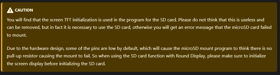
Could it be something related to this?

/*********************************/

Thanks beforehand, sorry for the inconveniences and looking forward to hearing from you.

Kind regards.

Daniel.

  • Hi Daniel,

    Have you tried to ensure that the Round Display driver is initialized before mounting the drive, like the caution warning have warned?

    If that doesn't fix it, could you please back track a little and verify that the micro-SD card feature works when the Round Display isn't presented in the Devicetree?

    Hieu


    Please be informed that our team is currently having reduced availability due to the Easter holiday. There will be some delays in our response during this time, but we will respond to you at the earliest opportunity. Our apologies for the inconvenience.

  • Hi Hieu,

    Thank you very much for your quick repply!

    Yeah, I was able to write in the micro SD card using the Arduino libraries since the example includes the TFT init method, which I presume, it manages everything related to the GPIO/SPI signals. The caution warning makes sense because the program stops working when that line (the "tft.init();" one) is removed from code.

    Example - SD card function section:

    https://wiki.seeedstudio.com/seeedstudio_round_display_usage/#all-xiao-series-in-addition-to-the-xiao-nrf52840-series

    The point here is that I am not using the Arduino library but the Zephyr OS one instead, so I do not know how to continue due to my lack of experience with TFT screeners in that operating system.

    Is there any work around for the micro SD? How can I proceed to develop something with this screen? All in Zephyr OS of course.

    Looking forward to hearing from you.

    Kind regards.

    Daniel.

  • Hi Daniel,

    By writing to the microSD card using the Arduino libraries, do you mean you have done that within the nRF Connect SDK (NCS) environment, or do you mean you have done that in the Arduino environment?

    What I previously suggest is to confirm that the microSD read-write feature work fine alone in NCS before integrating the round display.

    Not sure if I found the correct sample that you are referrencing, but I find a FAT FS sample latest presented in NCS v2.4.3, but have been replaced by/refactored into the FAT Filesystem Sample Application. If this is the correct reference, then notice this note in README:

    The sample should be able to run with any other board that has “zephyr,sdmmc-disk” DT node enabled.

    It seems you declare your SD card node with a different driver though. Did you also reference this from somewhere?

    Best regards,

    Hieu

  • Hi Hieu,

    Thank you very much for your reply! Let me answer the doubts / questions from your latest post:

    By writing to the microSD card using the Arduino libraries, do you mean you have done that within the nRF Connect SDK (NCS) environment, or do you mean you have done that in the Arduino environment?

    What I previously suggest is to confirm that the microSD read-write feature work fine alone in NCS before integrating the round display.

    I used the Arduino IDE and its own libraries (the ones that the Seeed Wiki suggests):

    https://wiki.seeedstudio.com/get_start_round_display/

    I presume they do not have anything to do with the nRF Connect SDK (NCS) environment, since I only installed that in the Visual Studio Code for the application that uses Zephyr OS.

    FYI:

    • I used the Arduino procedure in order to test both the boards and the micro SD card, just in case they might be damaged or something like that.
    • The round display board must be connected to the XIAO BLE Sense because is the one which contains the micro SD card circuitry.

    Not sure if I found the correct sample that you are referrencing, but I find a FAT FS sample latest presented in NCS v2.4.3, but have been replaced by/refactored into the FAT Filesystem Sample Application. If this is the correct reference, then notice this note in README:

    The sample should be able to run with any other board that has “zephyr,sdmmc-disk” DT node enabled.

    It seems you declare your SD card node with a different driver though. Did you also reference this from somewhere?

    Yes, the example you mention is the one I took as base, this is why my app.overlay file looks like quite similar (the driver you say is the same one), you may take a look:

    /*
     * Copyright (c) 2021 Nordic Semiconductor ASA
     *
     * SPDX-License-Identifier: Apache-2.0
     */
    
    / {
        chosen {
            zephyr,console = &cdc_acm_uart0;
        };
    };
    
    &zephyr_udc0 {
        cdc_acm_uart0: cdc_acm_uart0 {
        	compatible = "zephyr,cdc-acm-uart";
            label = "CDC_ACM_0";
        };
    };
    
    &spi2 {
        compatible = "nordic,nrf-spim";
        status = "okay";
        cs-gpios = <&gpio0 0x1C (GPIO_ACTIVE_LOW | GPIO_PULL_UP)>;
        pinctrl-0 = <&spi2_default>;
        pinctrl-1 = <&spi2_sleep>;
        pinctrl-names = "default", "sleep";
        sdhc0: sdhc@0 {
                compatible = "zephyr,sdhc-spi-slot";
                reg = <0>;
                status = "okay";
                mmc {
                    compatible = "zephyr,sdmmc-disk";
                    status = "okay";
                };
                spi-max-frequency = <24000000>;//8000000 /24000000 //16000000
        };
    };
    
    
    &spi2_default {
        group1 {
            psels = <NRF_PSEL(SPIM_SCK, 1, 13)>,
                <NRF_PSEL(SPIM_MOSI, 1, 15)>,
                <NRF_PSEL(SPIM_MISO, 1, 14)>;
            bias-pull-up;
        };
    };
    
    &spi2_sleep {
        group1 {
            psels = <NRF_PSEL(SPIM_SCK, 1, 13)>,
                <NRF_PSEL(SPIM_MOSI, 1, 15)>,
                <NRF_PSEL(SPIM_MISO, 1, 14)>;
            bias-pull-up;
            low-power-enable;
        };
    };

    I hope this information can give you more clues to find out what is going on, let me know if you need anything else.

    Looking forward to hearing from you.

    Kind regards.

    Daniel.

  • Hi Daniel,

    Thank you for your patience, and my apology for the long silence. Recovering from the Easter overloaded period took me much longer than I had hoped.

    I have resumed looking into this case and the direction I am trying to examine the order the Zephyr RTOS initialize the drivers and subsystems. It is my first time doing that, and I haven't figured out how to do it yet.

    By the way, have you tried to ask the Seeed community to see if someone there has an idea?

    I will continue to investigate, regardless.

    Best regards,

    Hieu

Related