Device tree setting problem

Hi 

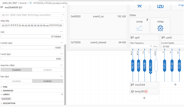
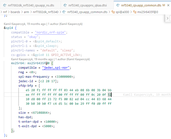
  Iam use nRF7002-DK, SDK v2.5.2, I try to set high seed SPI as master and connect with BMP280 sensor,I generate overay file for spi4 connect BMP280 sensor,for this resource in nrf5340_cpuapp_common.dts connect mx25r64 NOR flash first, as below picture, can I coonect two resource on this SPI4 or remove this NOR flash to other SPI resouce?If connect two on same SPI or remove the NOR falsh to other SPI resource, what the side effect happen for change setting? 
Best Regards

      Tina

Parents Reply Children
  • Hi Simonr

                  For this log,I really to write value to register as below.but when write to registers no any error message for write fail info.sometime registers value is "Zero" when I was solid connection the board and sensor.

    Define register

    #define CTRL3       0x22
    #define CTRL4       0x23
    #define CTRL5       0x24
    #define CTRL6       0x25
    #define CTRL7       0x26

    Write function

    static int lis_write_reg(uint8_t reg, uint8_t value)
    {
    int err;

    /* STEP 5.1 - declare a tx buffer having register address and data */
    uint8_t tx_buf[] = {(reg & 0x7F), value};
    struct spi_buf tx_spi_buf = {.buf = tx_buf, .len = sizeof(tx_buf)};
    struct spi_buf_set tx_spi_buf_set = {.buffers = &tx_spi_buf, .count = 1};
    /* STEP 5.2 - call the spi_write_dt function with SPISPEC to write buffers */
    err = spi_write_dt(&spispec, &tx_spi_buf_set);
    if (err < 0) {
    LOG_ERR("spi_write_dt() failed, err %d", err);
    return err;
    }
    LOG_ERR("spi_write_dt() SUCCESS, err %d", err);
    return 0;
    }

    In main

    {

        lis_write_reg(CTRL3, 0x9F);
        lis_write_reg(CTRL4, 0x9F);
        lis_write_reg(CTRL7, 0x9F);
    }
    Log for solid connection the board and sensor
    *** Booting nRF Connect SDK v2.5.2 ***
    [00:00:00.250,366] <inf> Lesson5_Exercise1: -------------------------------------------------------------
    [00:00:00.250,366] <inf> Lesson5_Exercise1: lis_read_calibrationdata: Reading from calibration registers:
    [00:00:00.250,396] <inf> Lesson5_Exercise1: Reg[0x0b] 2 Bytes read: Param T1 = 0
    [00:00:00.300,842] <inf> Lesson5_Exercise1: Reg[0x0f] = 0x00
    [00:00:00.321,044] <inf> Lesson5_Exercise1: Reg[0x1e] = 0x00
    [00:00:00.341,217] <inf> Lesson5_Exercise1: Reg[0x1f] = 0x00
    [00:00:00.361,389] <inf> Lesson5_Exercise1: Reg[0x20] = 0x00
    [00:00:00.381,591] <inf> Lesson5_Exercise1: Reg[0x21] = 0x00
    [00:00:00.401,763] <inf> Lesson5_Exercise1: Reg[0x22] = 0x00
    [00:00:00.421,936] <inf> Lesson5_Exercise1: Reg[0x23] = 0x00
    [00:00:00.442,108] <inf> Lesson5_Exercise1: Reg[0x24] = 0x00
    [00:00:00.462,310] <inf> Lesson5_Exercise1: Reg[0x25] = 0x00
    [00:00:00.482,482] <inf> Lesson5_Exercise1: Reg[0x26] = 0x00
    [00:00:00.502,655] <inf> Lesson5_Exercise1: Reg[0x27] = 0x00
    [00:00:00.522,827] <inf> Lesson5_Exercise1: Reg[0x28] = 0x00
    [00:00:00.543,029] <inf> Lesson5_Exercise1: Reg[0x26] = 0x00
    [00:00:00.563,201] <inf> Lesson5_Exercise1: Reg[0x27] = 0x00
    [00:00:00.583,404] <inf> Lesson5_Exercise1: Reg[0x28] = 0x00
    [00:00:00.603,546] <inf> Lesson5_Exercise1: Reg[0x29] = 0x00
    [00:00:00.623,748] <inf> Lesson5_Exercise1: Reg[0x2a] = 0x00
    [00:00:00.643,920] <inf> Lesson5_Exercise1: Reg[0x2b] = 0x00
    [00:00:00.664,093] <inf> Lesson5_Exercise1: Reg[0x2c] = 0x00
    [00:00:00.684,265] <inf> Lesson5_Exercise1: Reg[0x2d] = 0x00
    [00:00:00.704,467] <inf> Lesson5_Exercise1: Reg[0x2e] = 0x00
    [00:00:00.724,548] <inf> Lesson5_Exercise1: -------------------------------------------------------------
    [00:00:00.724,578] <inf> Lesson5_Exercise1: Continuously read sensor samples, compensate, and display
    [00:00:00.724,639] <inf> Lesson5_Exercise1: uncomp = 0 C
    [00:00:01.724,761] <inf> Lesson5_Exercise1: uncomp = 0 C
    [00:00:02.724,884] <inf> Lesson5_Exercise1: uncomp = 0 C
    [00:00:03.725,097] <inf> Lesson5_Exercise1: uncomp = 0 C
    Best Regards
          Tina
Related