Bluetooth AOA IQ samples

I am a BLE beginner and have some confusion about the IQ data of Bluetooth AOA. I used the example direction_finding_connectionless_rx and direction_finding_connectionless_tx from the SDK and I tried to print raw IQ data which contains 45 samples.

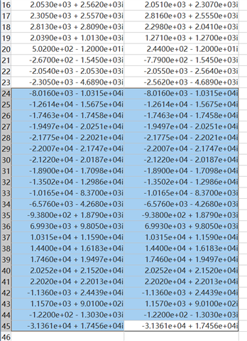
1. Why is the data in each frame exactly the same starting from 24? In the picture are 2 sets of data, I used printk("%d+%di\n", report->sample16[i].i, report->sample16[i].q) to print by console.

2. I also saw the existence of TSAMPLEOFFSET in the white paper, and saw CONFIG_BT_CTLR_DF_SAMPLE_OFFSET_PHY_2M_SAMPLING_2US=20 in the project's .config. The CTE of sending the beacon is 160us, but OFFSET is 20us. Does this mean that the effective sampling is 160us - 20us = 140us and the IQ samples the last 20us / 4 = 5 pieces of data are invalid?

3. Another question is about antenna switching. If I set ant_patterns to 0x1 0x2 0x3 0x4, will the sampled IQ array be 0x1 0x1 0x1 0x1 0x1 0x1 0x1 0x1 0x2 0x3 0x4 0x1 0x2 0x3 0x4 0x1 0x2 0x3 0x4 ..., because based on the white paper I'm not quite sure whether 0x1 should be included in the loop or not. And because the example uses a 2us slot by default, the first 8 data are sampled once every 1us, followed by every 4us, and part of the intermediate interval switching is 3us, right?And post-data processing requires phase correction due to the delay in sampling.

Kind regards,
Hao

Parents
  • Hello Hao,

    I am glad to see that you've had a look at the whitepaper on direction finding. Multiple customers miss that.

    1. Why is the data in each frame exactly the same starting from 24? In the picture are 2 sets of data, I used printk("%d+%di\n", report->sample16[i].i, report->sample16[i].q) to print by console.

    Maybe the same antenna patch is being sampled twice there. What is your antenna pattern? What antenna matrix are you using?

    2. I also saw the existence of TSAMPLEOFFSET in the white paper, and saw CONFIG_BT_CTLR_DF_SAMPLE_OFFSET_PHY_2M_SAMPLING_2US=20 in the project's .config. The CTE of sending the beacon is 160us, but OFFSET is 20us. Does this mean that the effective sampling is 160us - 20us = 140us and the IQ samples the last 20us / 4 = 5 pieces of data are invalid?

    CONFIG_BT_CTLR_DF_SAMPLE_OFFSET_PHY_2M_SAMPLING_2US is measured in number of 16M cycles. That is 20* 1/16.000.000 = 20* 62.5ns = 1.25µs.

    3. Another question is about antenna switching. If I set ant_patterns to 0x1 0x2 0x3 0x4, will the sampled IQ array be 0x1 0x1 0x1 0x1 0x1 0x1 0x1 0x1 0x2 0x3 0x4 0x1 0x2 0x3 0x4 0x1 0x2 0x3 0x4 ..., because based on the white paper I'm not quite sure whether 0x1 should be included in the loop or not. And because the example uses a 2us slot by default, the first 8 data are sampled once every 1us, followed by every 4us, and part of the intermediate interval switching is 3us, right?And post-data processing requires phase correction due to the delay in sampling.

    The pattern continues from how far its gotten after the reference period has ended. So eight samples with 0x1, then it loops from 0x2.

    0x1 0x1 0x1 0x1 0x1 0x1 0x1 0x1 0x2 0x3 0x4 0x2 0x3 0x4 

    If you are to make a Bluetooth compliant solution then the pattern should always rotate through the reference antenna, this can be done by having the reference antenna (pattern entry 2) as the last entry in the pattern table. It will then be part of the "looped" pattern. When you have gone through all the patterns loaded then the next IQ sample will be from pattern 3 and this will loop for the length of the CTE duration.

    Regards,

    Elfving

  • Thank you for your help. But I still have some problems.

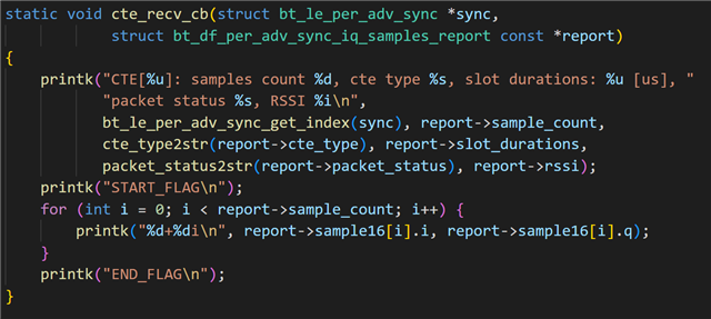
    1. As I mentioned question 1 before, I use the official Nordic 12 square array, and I only output 45 sampling points, but every time I output, the following IQ values are the same. I think this is not normal. My code is as follows:

    The serial port output is as follows:

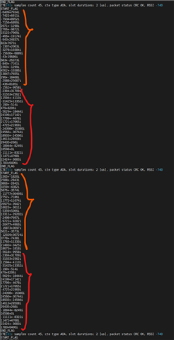
    The second half, the red part, is always the same, which is not corrrect I think. I began to think that it was because serial port printing took a long time, and the new data overwritten the buffer when the callback function was printing data. But I quickly ruled out this idea because I think the SDK should take this into account, that is, there are multiple buffers and use a queue, because the number of Bluetooth trains is set to 5, which means that 5 Bluetooth trains can arrive in a very short time. The buffers used by the callback function are not recycled until the callback function returns. But why is it always the same?

    2. You said that CONFIG_BT_CTLR_DF_SAMPLE_OFFSET_PHY_2M_SAMPLING_2US is measured in number of 16M cycles. Since the delay is 1.25µs, can it be considered that the actual sampling time is 160us - 1.25us? But I see that the output is still 45 points. Does this mean that the last point alaways invalid?

    3. The additional problem is the IQ data processing I mentioned. Because the Bluetooth antenna is time-division multiplexed, I want to do phase correction and beamforming, that is, each antenna rotates 2*pi*f*t on the IQ plane, and t is the time elapsed from the sampling moment of the antenna to the reference antenna sampling. I noticed that the example uses 2M PHY as the broadcast train physical layer. I learned from the white paper that theoretically f is 500kHZ. But considering the frequency offset, I tried to perform FFT on the first 8 points to obtain the actual f. Considering that the reference period is 1us once, which is a 1MHZ sampling rate, this does not seem to be well distinguished on the FFT spectrum. Is there a better way to get actual f or phase correction?

    Kind regards,

    Hao

  • hola , yo tengo un problema parecido y queria saber si pueden hecharme una mano ,,, tengo estas muestras de IQ:q": [195,73,-88,187,-170,-95,131,-184,188,137,-105,206,-140,-132,146,-188,-208,95,198,-95,-234,130,198,-112,-268,-23,244,21,-242,-33,224,10,-217,-92,226,54,-248,-28,163,84,-202,-140,178,205,-177,-95,94,117,-154,-131,36,244,-111,-209,53,316,-46,-206,-57,203,-2,-196,-67,268,119,-246,-62,179,165,-219,-84,168,120,-99,-145,171,232,-100,-187,70, 198,-77,-233,48],

    donde  CTElength ThelengthoftheCTE Unit:8us;2~20:turnonCTEsampling,0~1:turnoff. Unit:8us;2~20:turnonCTEsampling,0~1:turnoff.
    Sampling spacing = 2
    Switchspacing = 2

    Sample offset(in number of 16M cycles) = 1

    Switch offset(in number of 16M cycles) = 0

    Switch pattern = 2,2,0,5,6,1,4,12,9,14,13,8,10

    podria alguien explicarme a que antena pertenece cada IQ?

  • Please use English. The sequence of IQ values should from antena 2, 2, 2, 2, 2, 2, 2, 2, 2, 0, 5, 6, 1, 4, 12, 9, 14, 13, 8, 10, 2, 0, 5, 6, 1, 4, 12, 9, 14, 13, 8, 10, 2, 0, 5, 6, 1, 4, 12, 9, 14, 13, 8, 10 ... (until reach the end of CTE).

  • Thank you for responding, in this specific case it would be:

    for  Ant 2 (195,73,-88,187,-170,-95,131,-184,188,137,-105,206,-140, -132,146,-188,-208,95,198,-95)

    for Ant 0 = (,-234,130)  etc......

    [,198,-112,-268,-23,244,21,-242,-33,224,10,-217,-92,226,54,-248,-28,163, 84,-202,-140,178,205,-177,-95,94,117,-154,-131,36,244,-111,-209,53,316,-46,-206,-57,203,-2,-196,-67,268,119, -246,-62,179,165,-219,-84,168,120,-99,-145,171,232,-100,-187,70, 198,-77,-233,48]

  • What is the data format you describe? As I known, IQ data can obtain by cte_recv_cb report->sample16[i].ireport->sample16[i].q in SDK and the sequence of IQ values should from antena 2, 2, 2, 2, 2, 2, 2, 2, 2, 0, 5, 6, 1, 4, 12, 9, 14, 13, 8, 10, 2, 0, 5, 6, 1, 4, 12, 9, 14, 13, 8, 10, 2, 0, 5, 6, 1, 4, 12, 9, 14, 13, 8, 10 ... (until reach the end of CTE). How did you get this data? Are you using the SDK?

Reply
  • What is the data format you describe? As I known, IQ data can obtain by cte_recv_cb report->sample16[i].ireport->sample16[i].q in SDK and the sequence of IQ values should from antena 2, 2, 2, 2, 2, 2, 2, 2, 2, 0, 5, 6, 1, 4, 12, 9, 14, 13, 8, 10, 2, 0, 5, 6, 1, 4, 12, 9, 14, 13, 8, 10, 2, 0, 5, 6, 1, 4, 12, 9, 14, 13, 8, 10 ... (until reach the end of CTE). How did you get this data? Are you using the SDK?

Children
  • [{ "gateway":"ac233fc00001", "timestamp":"2021-01-08T05:38:05.443Z" },{ "mac":"c6c504030201", "timestamp":"2021-01-08T05:38:05.817Z", "no":2, "rssi":-69, "raw":"02010605ff3906cafb0809416f412d746167", "aoa":{ "frequency":2402, "iq":[-97,175,-173,-111,137,-165,168,145,-147,138,-135,-167,169,-143,131,171,-75,-194,66,235,-40,-249,34,228,2,-202,-16,211,36,-190,-36,170,141,-245,-86,180,117,-176,-149,146,178,-178,-204,132,201,-119,-194,83,204,-78,-185,14, 181,-27,-266,-29,201,23,-224,-38,186,89,-229,-94,190,149,-198,-118,134,171,-132,-177,86,165,-103,-157,73,254,-44,-200,42,224,-6,-205] } }

    I have used MQTT, I don't know if you would have any part of the code to get the angle and the xy position of the tag from this data, if I could abuse your wisdom to be able to make the code, I am using python....thanks
  • I think the better way to resolve your problem is consulting gateway developer. Because json data format depends on gateway developer's design which maybe use raw sdk to obtain data and combine json data.

Related