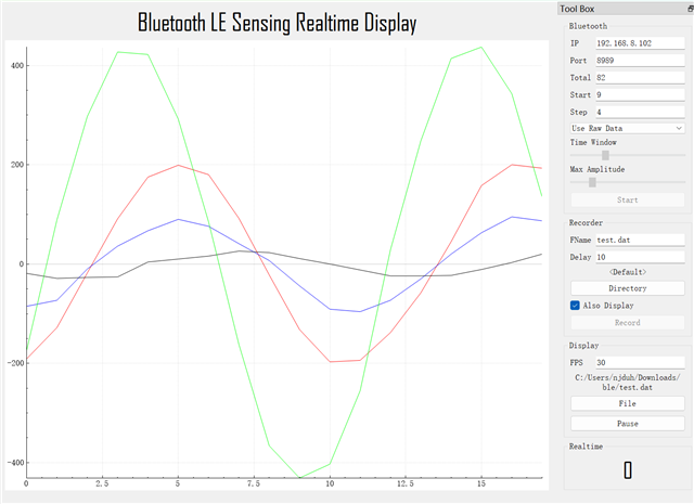
I am a BLE beginner and have some confusion about the IQ data of Bluetooth AOA. I used the example direction_finding_connectionless_rx and direction_finding_connectionless_tx from the SDK and I tried to print raw IQ data which contains 45 samples.
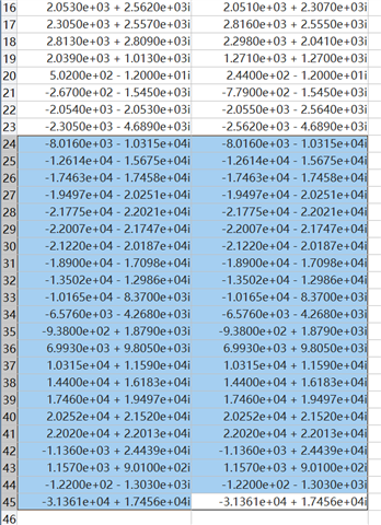
1. Why is the data in each frame exactly the same starting from 24? In the picture are 2 sets of data, I used printk("%d+%di\n", report->sample16[i].i, report->sample16[i].q) to print by console.
2. I also saw the existence of TSAMPLEOFFSET in the white paper, and saw CONFIG_BT_CTLR_DF_SAMPLE_OFFSET_PHY_2M_SAMPLING_2US=20 in the project's .config. The CTE of sending the beacon is 160us, but OFFSET is 20us. Does this mean that the effective sampling is 160us - 20us = 140us and the IQ samples the last 20us / 4 = 5 pieces of data are invalid?
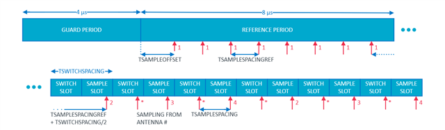
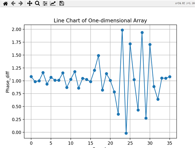
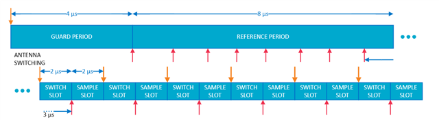
3. Another question is about antenna switching. If I set ant_patterns to 0x1 0x2 0x3 0x4, will the sampled IQ array be 0x1 0x1 0x1 0x1 0x1 0x1 0x1 0x1 0x2 0x3 0x4 0x1 0x2 0x3 0x4 0x1 0x2 0x3 0x4 ..., because based on the white paper I'm not quite sure whether 0x1 should be included in the loop or not. And because the example uses a 2us slot by default, the first 8 data are sampled once every 1us, followed by every 4us, and part of the intermediate interval switching is 3us, right?And post-data processing requires phase correction due to the delay in sampling.
Kind regards,
Hao