I am a BLE beginner and have some confusion about the IQ data of Bluetooth AOA. I used the example direction_finding_connectionless_rx and direction_finding_connectionless_tx from the SDK and I tried to print raw IQ data which contains 45 samples.
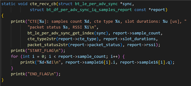
1. Why is the data in each frame exactly the same starting from 24? In the picture are 2 sets of data, I used printk("%d+%di\n", report->sample16[i].i, report->sample16[i].q) to print by console. I use the official Nordic 12 square array, and I only output 45 sampling points, but every time I output, the following IQ values are the same. I think this is not normal. My code is as follows:
The serial port output is as follows:
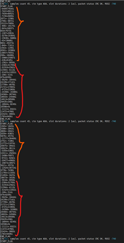
The second half, the red part, is always the same, which is not corrrect I think. I began to think that it was because serial port printing took a long time, and the new data overwritten the buffer when the callback function was printing data. But I quickly ruled out this idea because I think the SDK should take this into account, that is, there are multiple buffers and use a queue, because the number of Bluetooth trains is set to 5, which means that 5 Bluetooth trains can arrive in a very short time. The buffers used by the callback function are not recycled until the callback function returns. But why is it always the same?
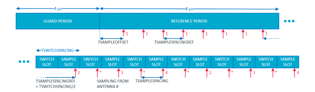
2. I also saw the existence of TSAMPLEOFFSET in the white paper, and saw CONFIG_BT_CTLR_DF_SAMPLE_OFFSET_PHY_2M_SAMPLING_2US=20 in the project's .config. Docs said that CONFIG_BT_CTLR_DF_SAMPLE_OFFSET_PHY_2M_SAMPLING_2US is measured in number of 16M cycles. Since the delay is 1.25µs, can it be considered that the actual sampling time is 160us - 1.25us? But I see that the output is still 45 points. Does this mean that the last point alaways invalid?
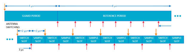
3. The additional problem is the IQ data processing. Because the Bluetooth antenna is time-division multiplexed, I want to do phase correction and beamforming, that is, each antenna rotates 2*pi*f*t on the IQ plane, and t is the time elapsed from the sampling moment of the antenna to the reference antenna sampling. I noticed that the example uses 2M PHY as the broadcast train physical layer. I learned from the white paper that theoretically f is 500kHZ. But considering the frequency offset, I tried to perform FFT on the first 8 points to obtain the actual f. Considering that the reference period is 1us once, which is a 1MHZ sampling rate, this does not seem to be well distinguished on the FFT spectrum. Is there a better way to get actual f or phase correction?
Kind regards,
Hao

