Two Button function coverage problem

Hey
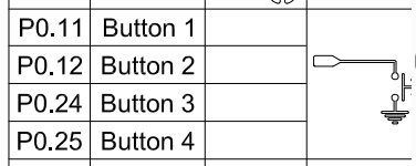
I've got this project that requires two buttons. In normal mode, these buttons react to the Ready pin switch signals. when it goes into sleep mode (where it controls other MCUs going to sleep), the UART Rx changes to act as a button to wake up based on High_Low signals of UART communication.

When it wakes up, the UART Rx Button switches back to being UART Rx pin for communication.

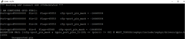
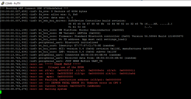
But here's the snag: when I change UART Rx to button, the original Ready pin detection button stops working, it just doesn't respond anymore.

If I try to add the initialization declaration for the Ready pin detection button after initializing UART Rx as a button, the UART Rx button loses its functionality.

Here's the code where I declare the buttons. Could you help me figure out where I need to make changes?

By the way, I'm using NCS v2.5.2. and Chip is nrf52840

The following is the code for the Ready Pin initialization and interrupt subroutine.

void CapSwReadyPin(const struct device *dev, struct gpio_callback *cb, uint32_t pins){
	int ret;
	int err = 0;	
	switch(u8CapSwStatus){
		case deCapSwNull:
		break;
		
		//have other case can change u8CapSwStatus...
		
		default:
		break;
}

void CapSwReadyPinInit(void){
	int ret;


	if (!gpio_is_ready_dt(&button)) {
		printk("Error: button device %s is not ready\n",
		       button.port->name);
		return 0;
	}
	
	ret = gpio_pin_configure_dt(&button, GPIO_INPUT);
	if (ret != 0) {
		printk("Error %d: failed to configure %s pin %d\n",
		       ret, button.port->name, button.pin);
		return 0;
	}
		ret = gpio_pin_interrupt_configure_dt(&button,GPIO_INT_EDGE_TO_ACTIVE );
	if (ret != 0) {
		printk("Error %d: failed to configure interrupt on %s pin %d\n",
			ret, button.port->name, button.pin);
		return 0;
	}

	gpio_init_callback(&button_cb_data, CapSwReadyPin, BIT(button.pin));
	gpio_add_callback(button.port, &button_cb_data);

}

The following is the code for initializing UART Rx as a button and setting up its interrupt subroutine.

void RxButtonInterrupt(const struct device *dev, struct gpio_callback *cb, uint32_t pins){
	u8SleepFlag = u8SleepFlag | deSleepSignal;
#if deSleepTest
	if(u8SleepTestFlag == deDisable){
		u8SleepTestFlag = deEnable;
		de_RLED_ON;
	}
	else{
		u8SleepTestFlag = deDisable;
		de_RLED_OFF;
	}
#endif	
}
void SleepButtoninit(void){
	int ret;
	if (!gpio_is_ready_dt(&RxButton)) {
		printk("Error: button device %s is not ready\n",
		       button.port->name);
		return 0;
	}
	
	ret = gpio_pin_configure_dt(&RxButton, GPIO_INPUT);
	if (ret != 0) {
		printk("Error %d: failed to configure %s pin %d\n",
		       ret, RxButton.port->name, RxButton.pin);
		return 0;
	}
		ret = gpio_pin_interrupt_configure_dt(&RxButton,GPIO_INT_EDGE_TO_ACTIVE );
	if (ret != 0) {
		printk("Error %d: failed to configure interrupt on %s pin %d\n",
			ret, RxButton.port->name, RxButton.pin);
		return 0;
	}

	gpio_init_callback(&button_cb_data, RxButtonInterrupt, BIT(RxButton.pin));
	gpio_add_callback(RxButton.port, &button_cb_data);
	
}
void SleepButtonUninit(void){
	int ret;
	if (!gpio_is_ready_dt(&RxButton)) {
		printk("Error: button device %s is not ready\n",
		       button.port->name);
		return 0;
	}
	
	ret = gpio_pin_configure_dt(&RxButton, GPIO_INPUT);
	if (ret != 0) {
		printk("Error %d: failed to configure %s pin %d\n",
		       ret, RxButton.port->name, RxButton.pin);
		return 0;
	}
		ret = gpio_pin_interrupt_configure_dt(&RxButton,GPIO_INT_MASK );
	if (ret != 0) {
		printk("Error %d: failed to configure interrupt on %s pin %d\n",
			ret, RxButton.port->name, RxButton.pin);
		return 0;
	}
}

The following is the code for the main program.

int main(void){
	int blink_status = 0;
	int err = 0;
	configure_gpio();
	de_GLED_ON;
	deSleepPinOFF;
	CapSwReadyPinInit();
#if deSempleCodeUR	
	err = uart_init();
	if (err) {
		error();
	}
#endif
#if deUartFunction
#if deMCU_URFunc
	MCU_UartInit();
#endif
#if	deRFID_Function
	RFID_UartInit();
#endif		
#endif
#if deI2C_Function
	I2C_Init();
#endif
	Timer_Init();
#if deMCU_TypeChackFunc
	u8TPSetTimNum = deTCRSMaxTime;
	u8TypeSetFlag = deEnable;
	while(u8TypeSetFlag==deEnable){
#if deMCU_URFunc
		MCU_UartDataProcess();
#endif	
#if deRFID_Function
		RFID_ModSwitch(deRFID_NormalMod);
#endif		
	}
	
#endif	
#if deBLE_Function
	BLE_FunctionSetting();
#endif	
#if deCapSwFunction
	de_CapSw_ON;
	deCapSwSetting;
#else
	de_CapSw_OFF;
#endif
	de_GLED_OFF;
	for (;;) {
#if deCapSwFunction		
		CapSwDataSend();
#endif	
#if deRFID_Function
		RFID_DataProcess();
#endif
#if deMCU_URFunc
		MCU_UartDataProcess();
#endif	
#if deBLE_Function
		BLE_ActFunction();
#endif	
#if deSlepButtonFunc
		SleepFunction();
#endif
	}
}

void SleepFunction(void){
	if(((u8SleepFlag & deSleepSignal)>0) && ((u8SleepLock & deSleepOn)== 0)){
		deMCU_UR_Off;
		SleepButtoninit();
		deSleepPinON;
		u8SleepFlag = u8SleepFlag & deSleepNormal;
		u8SleepLock = u8SleepLock | deSleepOn;
		// CapSwReadyPinInit();
	}
	else if(((u8SleepFlag & deSleepSignal)>0) && (u8SleepLock & deSleepOn)>0){
		SleepButtonUninit();
		MCU_UartInit();
		deSleepPinOFF;
		u8SleepFlag = u8SleepFlag & deSleepNormal;
		u8SleepLock = u8SleepLock & deSleepOff;
		// CapSwReadyPinInit();
	}
	
}

Parents Reply
  • Hi,

    Apologies for the delayed response.

    The issue is coming from configure_gpio() function that calls dk_buttons_init()

    This function would initialize buttons as on the DK.

    As you can see that on the DK (nrf52840dk), pins 11, 12, 24 and 25 are used for the four buttons.

    When you are calling the configure_gpio() function, three of the DK buttons are initialized while initializing the 4th one which you have defined gives error; of course this is not as on the DK, this is your definition.

    Error is also "Unsupported pin" that is pin 8.

    Hope if provides you direction in your debugging.

    Regards,

    Naeem

Children
  • Thank you for your response. The issue with the chip reset has been resolved. Unfortunately, when testing the required functionality with version 2.6.1, I’m still encountering the same problems as with 2.5.2.

    Using the nrf52840 development board, after powering it on and pressing Button1, LED4 lights up. After sending the command 80 03 02 35 23 81, LED2 lights up, and when Button2 is pressed, LED3 lights up. However, Button1 stops working and doesn’t respond. In the project, both buttons are supposed to work simultaneously.

    Could you please assist with this? I’ve updated and uploaded the code.

    Here’s the link:https://github.com/ItekRD/TwoButtonProblem

  • Hi,

    I have tried to go through your code, but I cannot review your whole code, it is not a short code.

    Also, when I flashed, I see different behavior than what you have described:

    When I reset the DK,

    LED4 is ON

    LED1 starts blinking

    if I press Button1 then LED4 toggles

    (meaning Button1 is working and in the callback we are toggling LED4)

    if I press Button2 in this state, it does nothing,

    next,

    when I connect with the device, LED2 turns ON,

    I can still use BUTTON1 to toggle LED4

    Button2 still does nothing,

    next,

    when I send that data "80 03 02 35 23 81" through RX characteristic, the device resets.

    You should probably debug your code by seeing how things go on.

    Also, maybe your Button2 is not configured properly.

    Can you first just test your buttons. Can you just show the sample code for buttons that produce that issue?

  • I might not have been very clear in my previous description. Here's the ideal behavior I'm aiming for:

    1.When I reset the DK, LED1 starts blinking, indicating that the chip is working properly.
    2.Button1 should toggle LED4, while Button2 does nothing.
    When I connect to the device and send the HEX data "80 03 02 35 23 81", 3.Button1 should still control LED4, and now Button2 should toggle LED3.
    4.Sending the same HEX data "80 03 02 35 23 81" again should revert to Button1 controlling LED4, and Button2 doing nothing.
    5This should cycle between steps 2 and 4.

    However, during my testing, here's what I observed:

    1.When I reset the DK, LED1 starts blinking, indicating that the chip is working properly.
    2.Button1 toggles LED4, while Button2 does nothing.
    When I connect to the device and send the HEX data "80 03 02 35 23 81", 3.Button1 stops working, and Button2 toggles LED3.
    4.Sending the HEX data "80 03 02 35 23 81" again results in both Button1 and Button2 not working.
    5.Sending the HEX data "80 03 02 35 23 81" again makes Button2 toggle LED3, but Button1 remains non-functional.
    6.Sending the HEX data "80 03 02 35 23 81" again returns to step 4, cycling through steps 4 to 6.


    This process does not cause the device to reset, and I couldn't reproduce the reset issue after multiple attempts.

    To check the code for the two buttons, search for "deButtonFunction" within the #if #endif section (lines 76 to 174). You'll notice that CapReadyPinInit (lines 97 to 124) and RxButtonEn (lines 147 to 174) have almost identical content. This code is derived from the Button Sample example. Button actions can be seen in CapRdyButtonInterrupt (lines 83 to 96) and RxButtonInterrupt (lines 83 to 96). UART functionality is within the #if deMCU_URFunc section (lines 178 to 348), with data handling in lines 263 to 303 and actions in lines 178 to 221. The reset might be caused here, though I couldn't reproduce it to confirm.

    If the issue is with button debugging, I want to use the declarations and debugging from the "BLE LED Button service" example. How can I disable the Button functionality? Which parts should I modify or disable, given that my project needs to switch between Rx and Button modes on the same pin?

    By the way, I'm using the nRF52840-DK board for testing.

    Please assist with this. Thank you.

  • I've tried a method that seems to work in testing, but I still have some concerns and would like to confirm a few things before proceeding.

    First, I'd like to ask if your data is being sent and received via Bluetooth or through UART or UARTE. In the example program, the Bluetooth functionality hasn't been modified, nor does it include the issue demonstration code.

    Here's the approach I took: I combined the button code from the "Button Sample" and "BLE LED Button Service" examples.

    1.After resetting the DK, the "CapReadyPinInit" function initializes the button, and I test it to ensure it works. This part of the code comes from the Button Sample.

    2.When I send "80 03 02 35 23 81" via UARTE, it directly initializes the buttons from the "BLE LED Button Service" example.

    err = dk_buttons_init(button_changed);
    if (err) {
        LOG_ERR("Cannot init buttons (err: %d)", err);
    }

    The button actions are handled in the "button_changed" function. This setup meets the project's requirements during testing.

    3. When I send "80 03 02 35 23 81" via UARTE again, I first disable the buttons with:

    err = dk_buttons_init(NULL);
    if (err) {
        LOG_ERR("Cannot init buttons (err: %d)", err);
    }

    4. Then, I reinitialize "CapReadyPinInit". This approach works in testing,

    but I have some doubts. Although both parts come from example programs, could there be stability issues when combining them? Or is it likely stable since both are from example programs?

    And I've updated the code on GitHub. Sorry for the inconvenience. Could you please take another look at it? Thanks!

  • Hi,

    I downloaded the code from your repo, and button1 is working before and after the connection.

    However, when I send those characters (80 03...) through ble, it results into hard-fault

    it is caused in line 857 (uart_tx)

Related