Beware that this post is related to an SDK in maintenance mode
More Info: Consider nRF Connect SDK for new designs

Can't get BLE device to sleep

I have a custom PCBA with which has the flow of:

- Boot

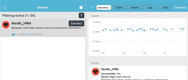
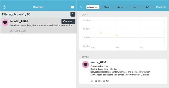
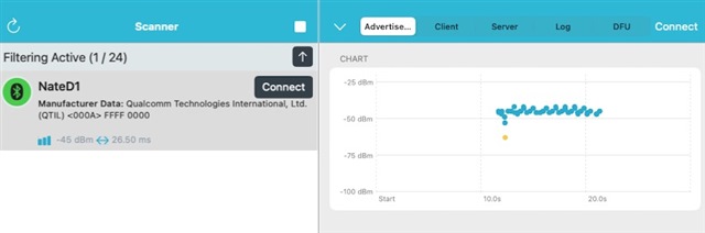
- Advertise some temperature data read from TWI with a 5 second timeout using `ble_adv_fast_timeout`.

- I then set a timer to wake the `app_timer_start(m_awake_timer_id, APP_TIMER_TICKS(SLEEP_IN_MS), NULL);`

And I expect the device to go into sleep whilst its BLE is not advertising. Here's my main.c file:

#include "app_timer.h"
#include "nrf_pwr_mgmt.h"
#include "nrf_crypto_init.h"
#include "nrfx_clock.h"

#include "SEGGER_RTT.h"
#include "nrf_log.h"
#include "nrf_log_ctrl.h"
#include "nrf_log_default_backends.h"
#include "nrf_delay.h"

#include "customble.h"
#include "peripheral.h"
#include "encryption.h"

void timers_init(void)
{
  ret_code_t err_code = app_timer_init();
  APP_ERROR_CHECK(err_code);
}

static void idle_state_handle(void)
{
  if (NRF_LOG_PROCESS() == false)
  {
    nrf_pwr_mgmt_run();
  }
}

/**@brief Function for initializing power management.
 */
void power_management_init(void)
{
  ret_code_t err_code;
  err_code = nrf_pwr_mgmt_init();
  APP_ERROR_CHECK(err_code);
}

int main(void)
{
  NRF_LOG_INIT(NULL);
  NRF_LOG_DEFAULT_BACKENDS_INIT();

  ret_code_t reta = nrf_crypto_init();
  APP_ERROR_CHECK(reta);

  timers_init();
  ble_timers_init();
  ble_stack_init();

  power_management_init();

  gap_params_init();
  advertising_init();

  advertising_start();

  for (;;)
  {
    idle_state_handle();
  }
}

and here's the relevant sections of the customble.c code

void awake_timer_handler()
{
  NRF_LOG_INFO("Awake and start advertising");

  update_advertising_data_while_advertising();
  advertising_start();
}

void sleep_timer_handler()
{
  NRF_LOG_INFO("asleep");

  sd_ble_gap_adv_stop(m_advertising.adv_handle); // i've tried with and without this

  // Proceed with setting the device to low power mode
  app_timer_start(m_awake_timer_id, APP_TIMER_TICKS(SLEEP_IN_MS), NULL); // 60 seconds
}

void on_adv_evt(ble_adv_evt_t ble_adv_evt)
{
  NRF_LOG_INFO("BLE EVENT");
  switch (ble_adv_evt)
  {
  case BLE_ADV_EVT_IDLE:
    NRF_LOG_INFO("Advertising event: Idle");
    sleep_timer_handler();
    break;
  }
}

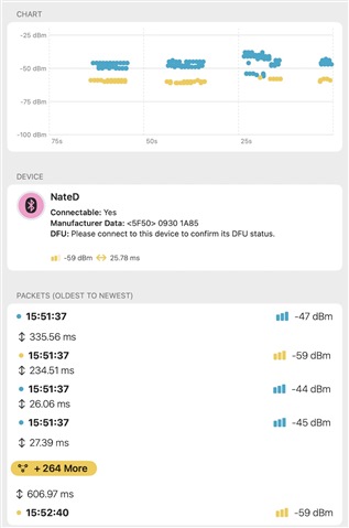
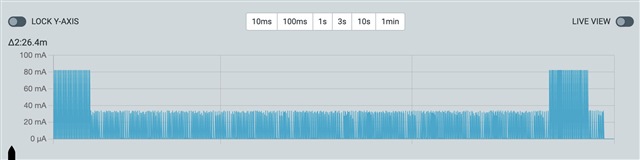
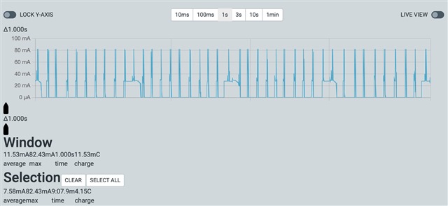
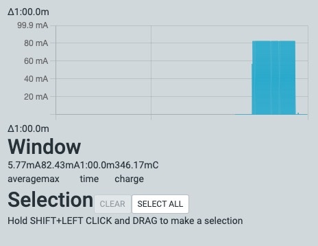
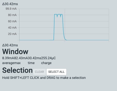
I have measured the amps on the device and during advertising it jumps to about 3mA and when it's not advertising (when I thought it would sleep) it's using ~1.48mA. What exactly am I doing wrong here?

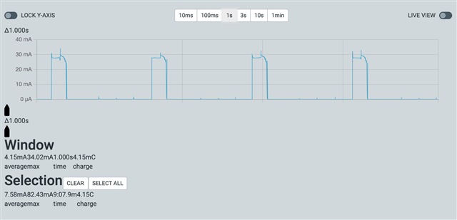
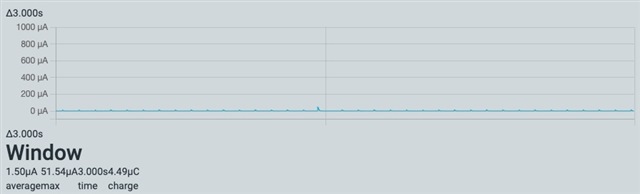
I have commented lots of things out, and it's not the TWI causing the issue, it's definitely the BLE. When I comment out starting BLE, I get ~400uA constant.

Parents
  • Hello,

    3A sounds like a lot. I don't think you are able to even draw that much through the nRF. Not 1.48A either. We should be talking about perhaps 20mA, or something around those numbers.

    Have you had your PCB design through a design review with Nordic? If not, perhaps you should create a ticket for that (so that it will be assigned to one of our HW engineers).

    Other than that, I can't say that I can see anything wrong with your application. Regarding the power, I see that you are using idle_state_handle() in your main-loop, so the device should enter sleep.

    I don't know what kind of crypto things you are doing, but to rule it out. Does it still draw as much power if you remove that as well? (just to make sure that the CPU isn't running all the time). 

    How do you measure the current consumption? Are you using the Power Profiler Kit 2? Or some other device?

    Best regards,

    Edvin

  • Eugh. Apologies, of course I mean mA not A. so ~3mA and 1.4mA. I'll edit my original answer.

    I'm using both a custom PCBA and also an NRF52DK (by following the document to cut the connection then measure over the power consumption pins). I will take another reading using the DK but the power wasn't too different to what I was seeing on my custom PCBA (with no sleep happening).

    In terms of the crypto, it's not that, I've checked this also. It's definitely the BLE that's causing the device not to go into sleep mode.

  • Advertising every 5 seconds is pretty slow. I see that you tried experimenting with different advertising intervals. Have you tried running one of the simpler samples on your custom board?

    I misspoke when I said this, sorry. I meant timeout, not interval. So 5 seconds advertising (100ms interval) - sleep for 10 seconds - repeat.

    I noticed a warning when building your application again, that NRFX_RNG_ENABLED was defined more than once.

    I believe that to not be an issue, it's when I was setting up the crypto libraries. I believe it's when I define both

    #define RNG_ENABLED 1
    #define NRFX_RNG_ENABLED 1

    They're the same thing?

    That being said, here is the output of the application you requested:

    <info> app: NRFX_RNG_ENABLED 1
    <info> app: CLOCK_CONFIG_LF_SRC 0
    <info> app: NRF_SDH_CLOCK_LF_SRC 0
    <info> app: NRF_SDH_CLOCK_LF_RC_CTIV 16
    <info> app: NRF_SDH_CLOCK_LF_RC_TEMP_CTIV 2
    <info> app: NRF_SDH_CLOCK_LF_ACCURACY 1
    <info> app: checking LFCLK ...
    <info> app: LFCLK started!
    <info> app_timer: RTC: initialized.
    <info> CLOCK: Function: nrfx_clock_init, error code: NRF_SUCCESS.
    <info> clock: Function: nrf_drv_clock_init, error code: NRF_SUCCESS.
    <info> app: my addr: D0:07:B7:A4:FC:E2
    <info> app: Starting temperature measurement.
    

    If you are still not able to see the advertisements, can you please test the attached project? It should start blinking the LEDs every 1 second (2 second period). Does it seem correct? Or is it way to fast/slow?

    I couldn't quite get that project setup, so I quickly wrote another one to run on my PCBA that does the same (blinks the light using app timers every 1000ms:

    #include "nrf_drv_clock.h"
    #include "app_timer.h"
    #include "nrf_gpio.h"
    #include "boards.h"
    
    #define LED_PIN 6 // LED connected to pin 6
    APP_TIMER_DEF(m_led_toggle_timer);
    
    static void led_toggle(void * p_context)
    {
        UNUSED_PARAMETER(p_context);
        nrf_gpio_pin_toggle(LED_PIN);
    }
    
    static void timers_init(void)
    {
        // Initialize the app timer module.
        ret_code_t err_code = app_timer_init();
        APP_ERROR_CHECK(err_code);
    
        // Create the timer to toggle the LED every 1 second.
        err_code = app_timer_create(&m_led_toggle_timer, APP_TIMER_MODE_REPEATED, led_toggle);
        APP_ERROR_CHECK(err_code);
    }
    
    static void gpio_init(void)
    {
        // Initialize the GPIO pin as output with initial value as low (LED off)
        nrf_gpio_cfg_output(LED_PIN);
        nrf_gpio_pin_clear(LED_PIN);
    }
    
    int main(void)
    {
        // Initialize the LFCLK required for the timers.
        nrf_drv_clock_init();
        nrf_drv_clock_lfclk_request(NULL);
    
        gpio_init();
        timers_init();
    
        // Start the timer
        ret_code_t err_code = app_timer_start(m_led_toggle_timer, APP_TIMER_TICKS(1000), NULL);
        APP_ERROR_CHECK(err_code);
    
        // Enter main loop.
        while (true)
        {
        }
    }
    

    and the output looks good to me:

    Edit:

    I got the ble_app_hrs_pca10040e_s112 example working on both the DK and custom PCBA. First image is on the DK and second is on the custom PCBA (I removed DEVELOP_IN_NRF52832 when on the PCBA as needed).

  • prsboy said:
    and the output looks good to me

    Ok, that looks good. I can't tell from your snippet, but that is using the RC-oscillator, and not the SYNTH LFCLK_SRC, right?

    Just so I didn't misunderstand something. When you initially tested your own application, and the issue was the high current consumption. Were you able to pick up more advertising packets then? When you were using the SYNTH source for the LF clock? Or was the performance the same?

  • Ok, that looks good. I can't tell from your snippet, but that is using the RC-oscillator, and not the SYNTH LFCLK_SRC, right?

    Correct, with the RC oscillator.

    When you initially tested your own application, and the issue was the high current consumption. Were you able to pick up more advertising packets then? When you were using the SYNTH source for the LF clock? Or was the performance the same?

    Yes, when setting the LFCLK to SYNTH everything behaves exactly how I'd expect. I've attached two scans, the first one is my custom PCBA with SYNTH, the second is using the RC oscillator:

    SYNTH

    #define CLOCK_CONFIG_LF_SRC 2
    #define NRF_SDH_CLOCK_LF_SRC 2
    #define NRF_SDH_CLOCK_LF_RC_CTIV 0
    #define NRF_SDH_CLOCK_LF_RC_TEMP_CTIV 0
    #define NRF_SDH_CLOCK_LF_ACCURACY 5
    -----
    #define ADV_TIMEOUT 1000
    #define SLEEP_IN_MS 10000

    As you can see from the screenshot, it's advertising for 10 seconds then sleeping for 10 seconds.
     
    RC oscillator

    #define CLOCK_CONFIG_LF_SRC 0
    #define NRF_SDH_CLOCK_LF_SRC 0
    #define NRF_SDH_CLOCK_LF_RC_CTIV 16
    #define NRF_SDH_CLOCK_LF_RC_TEMP_CTIV 2
    #define NRF_SDH_CLOCK_LF_ACCURACY 1
    -----
    #define ADV_TIMEOUT 1000
    #define SLEEP_IN_MS 10000
    just to add more intrigue into this, when running the RC oscillator, with the same configuration as above, nothing shows up.
    If I update the advertising timeout to 20 seconds,
    #define ADV_TIMEOUT 2000
    #define SLEEP_IN_MS 10000
    I get this:
     
    Note the duration of this scan 38 minutes and it detected 35 advertisement packets. When I use the synthesised clock I get that in a few seconds.
    Whilst this update frequency would be fine, the problem is when I then reduce the sleep to 120 seconds to preserve battery, it'll be a much longer period of time before an advertisement is picked up.

    Edit:
    I decided I was just going to play around with the rc configuration. The following configuration works* best for my device:
    #define CLOCK_CONFIG_LF_SRC 0
    #define NRF_SDH_CLOCK_LF_SRC 0
    #define NRF_SDH_CLOCK_LF_RC_CTIV 1
    #define NRF_SDH_CLOCK_LF_RC_TEMP_CTIV 0
    #define NRF_SDH_CLOCK_LF_ACCURACY 9
    With these values, and setting the original settings of 10 seconds advertising, 10 seconds sleep I get the following:
    Now, it's nowhere near as good as using the synthesised lfclk, but at least i'm detecting multiple packets per advertisements each wake cycle.
    * As with everything, there's a cost to this - the "sleep" cycle is almost non-existent as it hops from sleep into what I imagine is a wake calibrate the rc oscillator. This is the power being used whilst in sleep:
    To my fairly uneducated mind, this configuration change and increase in packets received does suggest that the rc oscillator is not stable enough with the recommended settings - does that make sense?
  • I find this very odd.

    Do you happen to have a PPK2? If so, can you please capture some graphs from running on SYNTH, and from running the RC_OSCILLATOR? A multimeter doesn't really give a clear picture of what's going on.

    If you have not already, I suggest that you also create a new ticket where you upload your schematics and PCB layout and ask for a layout review. I am not sure what it would be, but perhaps one of our HW engineers can spot something that I have not thought of. 

    Have you tried to capture a sniffer trace of the advertisements? You can do so using the nRF Sniffer for Bluetooth LE. If possible, can you upload one trace usnig SYNTH and one using the RC_OSCILLATOR?

    BR,
    Edvin

  • Indeed, very strange.

    Do you happen to have a PPK2? If so, can you please capture some graphs from running on SYNTH, and from running the RC_OSCILLATOR? A multimeter doesn't really give a clear picture of what's going on.

    Will a PPK1 do? I can get ahold of one of those in a few days.

    Have you tried to capture a sniffer trace of the advertisements? You can do so using the nRF Sniffer for Bluetooth LE. If possible, can you upload one trace usnig SYNTH and one using the RC_OSCILLATOR?

    I will get those sniffer traces uploaded for both SYNTH and RC. 

    If you have not already, I suggest that you also create a new ticket where you upload your schematics and PCB layout and ask for a layout review. I am not sure what it would be, but perhaps one of our HW engineers can spot something that I have not thought of. 

    How do I request a specific hardware review?

Reply
  • Indeed, very strange.

    Do you happen to have a PPK2? If so, can you please capture some graphs from running on SYNTH, and from running the RC_OSCILLATOR? A multimeter doesn't really give a clear picture of what's going on.

    Will a PPK1 do? I can get ahold of one of those in a few days.

    Have you tried to capture a sniffer trace of the advertisements? You can do so using the nRF Sniffer for Bluetooth LE. If possible, can you upload one trace usnig SYNTH and one using the RC_OSCILLATOR?

    I will get those sniffer traces uploaded for both SYNTH and RC. 

    If you have not already, I suggest that you also create a new ticket where you upload your schematics and PCB layout and ask for a layout review. I am not sure what it would be, but perhaps one of our HW engineers can spot something that I have not thought of. 

    How do I request a specific hardware review?

Children
  • prsboy said:

    Will a PPK1 do? I can get ahold of one of those in a few days.

    Yes. That works too. The PPK2 is a bit easier to use, but the PPK 1 will still give accurate readings, and perhaps show some patterns that can reveal something.

    prsboy said:
    How do I request a specific hardware review?

    Just create a ticket here on DevZone (but make it private, unless you want your design to be out in the public), and add your PCB layout files and your schematics. If you didn't design the HW, then talk to the people who did, and they probably know what files we are talking about. And if something is missing, the HW engineer from our side that is assigned to the ticket will know what additional files to request. 

    However, before you do this. Did you test this on one device, or do you have several custom boards? It would be interesting to know whether this behavior is only present on one nRF Chip, or several. 

    BR,
    Edvin

Related