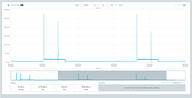
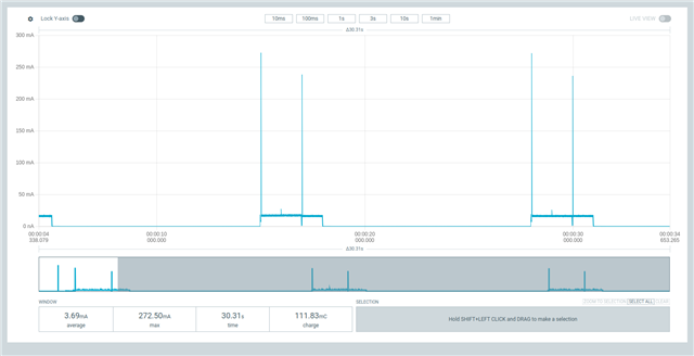
SPI CS pin input vs output inactive power consumption

Hi,

I was checking the HAL for SPI in master mode and notice that when pm_device_action_run(<spi_device>, PM_DEVICE_ACTION_SUSPEND); the CS pin isnt changed since it status change after every transmission to output inactive : https://github.com/nrfconnect/sdk-zephyr/blob/v3.5.99-ncs1/drivers/pinctrl/pinctrl_nrf.c#L136

On the other hand, in the spim driver the SS pin is set as input when the pm action is to suspend: https://github.com/nrfconnect/sdk-hal_nordic/blob/8f013ea950f41bf69b18bf688bfb0dd80a3fdc44/nrfx/drivers/src/nrfx_spim.c#L465 . However, the code never reaches this point because the pinctrl is taking care of setting the pins to suspend state.

My question is what is the difference between both, how setting the pin as input differ as setting the pin as ouput inactive.

Thank you!

Parents
  • Hi,

    The SS pin is controlled as a regular GPIO by the driver, not by the SPIM peripheral itself like MISO, MOSI, and CLK. Therefore, it is not the responsibility of the pinctrl module to configure this pin. The driver should probably have reconfigured this pin to its reset state to match the behavior when pinctrl is not enabled.

    My question is what is the difference between both, how setting the pin as input differ as setting the pin as ouput inactive.

    Output inactive corresponds to an active low output, i.e., the SS signal will be driven low.  

    But why do you need to suspend the SPIM peripheral? Are you experiencing high sleep currents between SPIM transactions?

    Best regards,

    Vidar

    Edit: The chip select signal is almost always active low, which means the pin will be driven high when set to inactive. Whether this will lead to any additional current consumption or not depends on the SS input on your SPI slave sensor. 

  • Hi,
    Thanks for the reply. I understand that the SS pin is controlled by pintctrl or as a normal GPIO (like I mentioned in the question and added the sourced code where this is done). But my question is why the SPIM driver puts the SS pin as input while the pinctrl puts it as output inactive. Also, I believe a GPIO pin set as input will consume less energy compared to GPIO set as output low ?
    From the dataseeht there is also this info:
    The input buffer of a GPIO pin can be disconnected from the pin to enable power savings when the pin is
    not used as an input


    So Im kind confused what approach should be the best one to achieve a low power consumption.

    Thank you!

  • Miguel Ferreira said:
    So Im kind confused what approach should be the best one to achieve a low power consumption.

    This should be measured on your setup. Disconnecting the SS pin on the nRF may lead to a floating input on your SPI flash sensor.

Reply Children
Related