Using nrf5340dk with the nrf21540 EK

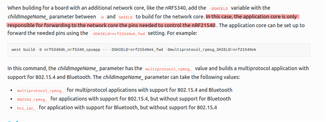
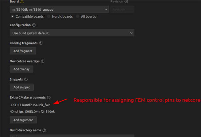
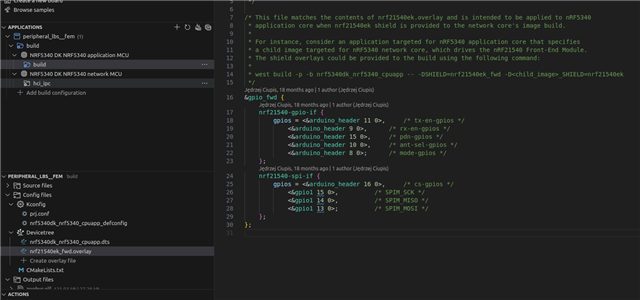
Hey I have a question regarding the setup described in the title. I have an application built upon the "Throughput Sample" of Nordic Semiconductor. To get a farther Distance, the Receiver gets an nrf21540 EK, connected via the Arduino Headers and a SMA cable. Now I added the Shield via Extra C-Make option in The VS Code Extension:

-DSHIELD=nrf21540ek and
-Dhci_ipc_SHIELD=nrf21540ek

However, this is the only thing I did so far. The resources online are diverse and I don't know where to start. Can i just plug it in now and it automatically
works? Do i need to change something in my code for it to work?
I use the 2.6.0 SDK in Visual Studio Code

An answer would help a lot! Thanks!
Parents
  • Hello,

    You need to select the nrf21540ek_fwd shield for your parent image running on the application core.

    From the SDK documentation: 

    https://developer.nordicsemi.com/nRF_Connect_SDK/doc/latest/nrf/device_guides/working_with_fem.html#programming 

    Build configuration to select relevant FEM shield for app and netcore

    Checking default MPSL FEM settings in generated .config output for BT controller on netcore

    DT overlay applied to netcore from selected shield

    DT overlay applied to appcore for pin forwarding from selected shield

    Best regards,

    Vidar

  • I see, I'll try that, that does help a lot thanks!

     Regarding the next steps, I have two general questions, only if you have time to answer:

    1. )  I don't get the difference between 

    CONFIG_MPSL_FEM_NRF21540_TX_GAIN_DB and 
    CONFIG_MPSL_FEM_NRF21540_TX_GAIN_DB_POUTA or 
    CONFIG_MPSL_FEM_NRF21540_TX_GAIN_DB_POUTB respectively, what do they represent? Why are there 3? And more important, how does it relate to the 
    CONFIG_BT_CTLR_TX_PWR_ANTENNA? Do these values add up?
    2.) How do I select which antenna i want? Is the switching between the antennas automatic (regarding antenna diversity)
  • The default values for CONFIG_MPSL_FEM_NRF21540_TX_GAIN_DB_POUTA and CONFIG_MPSL_FEM_NRF21540_TX_GAIN_DB_POUTB represents the factory-precalibrated gain values for the nRF21540 PA. CONFIG_MPSL_FEM_NRF21540_TX_GAIN_DB is used to select which one of these pre-calibrated values you want to use (i.e. +10 dBM or +20 dBm).

    CONFIG_BT_CTLR_TX_PWR_ANTENNA should be set equal to CONFIG_MPSL_FEM_NRF21540_TX_GAIN_DB if you want to +10 or +20 dBm on the antenna. 

    We currently don't have any protocol stacks that use antenna diversity. 

Reply
  • The default values for CONFIG_MPSL_FEM_NRF21540_TX_GAIN_DB_POUTA and CONFIG_MPSL_FEM_NRF21540_TX_GAIN_DB_POUTB represents the factory-precalibrated gain values for the nRF21540 PA. CONFIG_MPSL_FEM_NRF21540_TX_GAIN_DB is used to select which one of these pre-calibrated values you want to use (i.e. +10 dBM or +20 dBm).

    CONFIG_BT_CTLR_TX_PWR_ANTENNA should be set equal to CONFIG_MPSL_FEM_NRF21540_TX_GAIN_DB if you want to +10 or +20 dBm on the antenna. 

    We currently don't have any protocol stacks that use antenna diversity. 

Children
  • I see, so is it only possible to choose these 2 values?

    Because in my country there is the regulation that the maximum E.I.R.P is 100mW, so 20dbm. As my antenna has a dbi of 7, i want to set the gain value to 13 (so that the total strength is 20). Is this possible? Thanks

    If you don't support antenna diversity, what is the reason to have 2 antenna ports on the 21540? 

  • You can calibrate the FEM in production for other fixed output values. The FEM power model can also be used to get the desired output power. The model will adjust the gain from the nRF RADIO to accomplish this.

    The maximum output power depends on which RF protocol you are using, please refer to the 'Maximum regulatory TX output power' table at this page: https://www.nordicsemi.com/Products/Wireless/Range-extenders 

    If you don't support antenna diversity, what is the reason to have 2 antenna ports on the 21540? 

    Sorry, I found now that antenna diversity support is available for 15.4: https://developer.nordicsemi.com/nRF_Connect_SDK/doc/latest/nrfxlib/nrf_802154/doc/antenna_diversity.html#ant-diversity-algorithm. Antenna diversity is primarily useful if you have two stationary devices communicating on a single frequency; if you are moving or frequency-hopping, you might as well retransmit as change antennas.

  • Sorry, it still isn't quite clear to me how to calibrate it as it does not make sense to me how to apply it. I want to have the FEM provide a 13dbm output power for Bluetooth LE. Can I just set the CONFIG_BT_CTLR_TX_PWR_ANTENNA to 13, and the CONFIG_MPSL_FEM_NRF21540_TX_GAIN_DB to 20 as default? Will that ensure me the desired output? All these different Config variables seem conflicting to me, I apologise that i have to ask again.

    I don't need to change the output power dynamically, I only want to set it once statically.

    Regarding the antenna diversity: As i Understand, this is only for 802.15.4? This won't work for Bluetooth LE right?

    Thanks and again sorry for the many questions

  • I agree that it can be confusing what configuration settings to use with the FEM. I don't think you need to change the factory calibration, I just wanted to mention it is an option. 

    Sorry, it still isn't quite clear to me how to calibrate it as it does not make sense to me how to apply it. I want to have the FEM provide a 13dbm output power for Bluetooth LE. Can I just set the CONFIG_BT_CTLR_TX_PWR_ANTENNA to 13, and the CONFIG_MPSL_FEM_NRF21540_TX_GAIN_DB to 20 as default? Will that ensure me the desired output?

    Yes, the RADIO.TXPOWER register will then be set to -7 to acheive the desired output. Note that +10 dBm is the max. output power permitted for BLE in Europe.

    Regarding the antenna diversity: As i Understand, this is only for 802.15.4? This won't work for Bluetooth LE right?

    Correct. Antenna diversity isn't that useful for BLE due to channel hopping and short preamble. I haven't seen anyone using it with BLE.