GPIO conflict

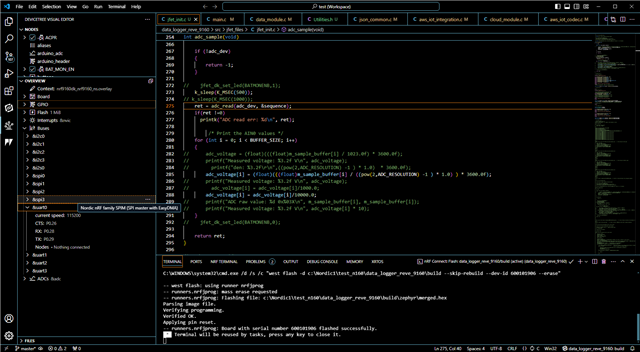
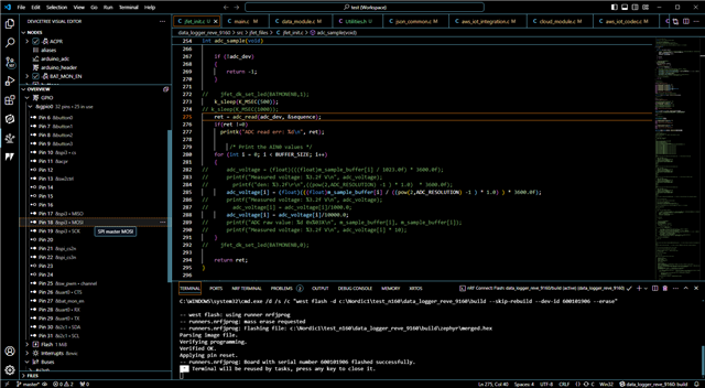
I have a nRF9160DK board that is used for development of a custom nRF9160 board. The hardware designers have assigned GPIO P0.27 to be a general purpose output pin. This pin is also used as uart0_cts. when I try to toggle this pin with a simple test it does not work with the code shown below. If I use another pin such as P0.23 the pin toggles fine. I am assuming there is a pin conflict by assigning 2 things to the same pin. The boards are already manufactured with P0.27 as a general purpose output control pin. How can I get this to work? Is there something in the overlay file I need to add or remove?

    int test = 0;
    while(1)
    {
        printf("test GPIO BAT_MON_EN %d\r\n",test & 0x01);
        /* toggle test */

        /* set/clear test */
        if(test++ & 0x01)
        {
//          printf("set\r\n");
            gpio_pin_set(bat_mon_en_dev, BAT_MON_EN_DEV_PIN, 1);
        }
        else
        {
//          printf("clear\r\n");
            gpio_pin_set(bat_mon_en_dev, BAT_MON_EN_DEV_PIN, 0);
        }
        k_sleep(K_MSEC(1000));
    }
Parents
  • Hello,

    Did you do anything to disable the UART0 CTS pin before trying to use it as an output pin? If not, then the GPIO is probably controlled by the UART, and you will not be able to control it. 

    If you look in the file nrf9160dk_nrf9160_common-pinctrl.dtsi, you will see the definition of uart0_default and uart0_sleep close to the top. Don't change this file (you can for testing, but I don't recommend doing so permanently), but copy the part about uart0:

    &pinctrl {
    	uart0_default: uart0_default {
    		group1 {
    			psels = <NRF_PSEL(UART_TX, 0, 29)>,
    				<NRF_PSEL(UART_RTS, 0, 27)>;
    		};
    		group2 {
    			psels = <NRF_PSEL(UART_RX, 0, 28)>,
    				<NRF_PSEL(UART_CTS, 0, 26)>;
    			bias-pull-up;
    		};
    	};
    
    	uart0_sleep: uart0_sleep {
    		group1 {
    			psels = <NRF_PSEL(UART_TX, 0, 29)>,
    				<NRF_PSEL(UART_RX, 0, 28)>,
    				<NRF_PSEL(UART_RTS, 0, 27)>,
    				<NRF_PSEL(UART_CTS, 0, 26)>;
    			low-power-enable;
    		};
    	};

    And create a file called "nrf9160dk_nrf9160.overlay" in your application folder (same folder as your prj.conf). Then paste this snippet that you just copied, and add a final line with "};" at the end to close off the bracket. Then try to remove everything about UART_RTS and UART_CTS (make it look like the uart2 definition in the original nrf9160dk_nrf9160_common-pinctrl.dtsi file):

    &pinctrl {
    	uart0_default: uart0_default {
    		group1 {
    			psels = <NRF_PSEL(UART_TX, 0, 29)>,
    				<NRF_PSEL(UART_RX, 0, 28)>;
    		};
    	};
    
    	uart0_sleep: uart0_sleep {
    		group1 {
    			psels = <NRF_PSEL(UART_TX, 0, 29)>,
    				<NRF_PSEL(UART_RX, 0, 28)>;
    			low-power-enable;
    		};
    	};
    };

    save the file, and delete your build folder, and build from scratch. Does that allow you to toggle pin P0.27?

    Best regards,

    Edvin

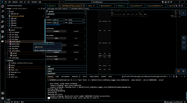
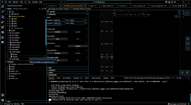
  • I have attached my overlay file. The BAT_MON_EN (P0.27) does not work when I toggle with the code above. The other pins seem to work just fine. what am I doing wrong?

    6278.nrf9160dk_nrf9160_ns.overlay

Reply Children
Related