thingy53 using twic qwiic boards.

I am using a thingy53 and trying to get i2c devices to work via the qwiic/twic interface.

I bought:
SparkFun Qwiic Buzzer - BOB-24474 - SparkFun Electronics and https://www.sparkfun.com/products/14558

I know that they are connected correctly using the qwiic cable since I can't flip the connector as it is keyed.
The RTC is 0x69 and the buzzer is at address 0x34.
I've tried them separately and individually, the buzzer has a lit power led and I've verified 3.3v on the rtc board.

I'm using the shell as described here: How to use Zephyr shell for interactive prototyping with I2C sensors - Golioth

i2c scan i2c@9000
0 1 2 3 4 5 6 7 8 9 a b c d e f
00: -- -- -- -- -- -- -- -- -- -- -- --
10: 10 -- -- -- -- -- -- -- -- -- -- -- -- -- -- --
20: -- -- -- -- -- -- -- -- -- -- -- -- -- -- -- --
30: -- -- -- -- -- -- -- -- 38 -- -- -- -- -- -- --
40: -- -- -- -- -- -- -- -- -- -- -- -- -- -- -- --
50: -- -- -- -- -- -- -- -- -- -- -- -- -- -- -- --
60: 60 -- -- -- -- -- -- -- -- -- -- -- -- -- -- --
70: -- -- -- -- -- -- 76 --
4 devices found on i2c@9000

i2c scan always returns only 4 devices, the ones that come defined as default in thingy53_nrf5340_common.dtsi.
I can read and interact with these devices just fine.

I have tried many things like placing the following in the overlay.   (thingy53_nrf5340_cpuapp.overlay)
&i2c1 {
buzz34: buzz34@34 {
compatible= "i2c-device";
reg = <0x34>;
label = "BUZZ34";
};
};

Or modifying the dtsi file directly adding in the devices there.

&i2c1 {
    compatible = "nordic,nrf-twim";
    status = "okay";
    clock-frequency = <I2C_BITRATE_FAST>;

    pinctrl-0 = <&i2c1_default>;
    pinctrl-1 = <&i2c1_sleep>;
    pinctrl-names = "default", "sleep";
    bmm150: bmm150@10 {
        compatible = "bosch,bmm150";
        reg = <0x10>;
    };

    bh1749: bh1749@38 {
        compatible = "rohm,bh1749";
        reg = <0x38>;
        int-gpios = <&gpio1 5 (GPIO_PULL_UP | GPIO_ACTIVE_LOW)>;
    };

    bme688: bme688@76 {
        compatible = "bosch,bme680";
        reg = <0x76>;
    };
    rv1805: rv1805@69 {
        compatible= "i2c-device";
        reg = <0x69>;
        label = "RV1805";
    //  compatible= "ambiq,am1805";
    //  // am1805-gpios = <&gpio1 15 (GPIO_PULL_UP | GPIO_ACTIVE_HIGH)>;
    //  reg = <0x69>;
    //  status = "okay";
    };
    buzz34: buzz34@34 {
        compatible= "i2c-device";
        reg = <0x34>;
        label = "BUZZ34";
    };
};


I am using an RV1805 and not a AM1805.  At this point I'm just trying to get the devices to show up in the scan as a simple i2c-device.
This all compiles and runs but does not show the devices on the i2c scan.

When I do use the ambiq,am1805 driver, it shows in the device list as disabled and still remains unseen in the scan.

I saw some other issues refer to CONFIG_I2C_NRFX=y; I tried this and it does not help.

  • Hi,

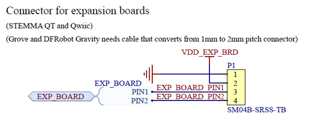
    According to the Thingy53 HW files, the expansion board header is connected to GPIOs P0.04 and P0.05:

    The other I2C sensor on the board are connected to P1.02/P1.03 (default pins for I2C1 node). To interface the sensors connected to the expansion board connector, you should use a separate i2c instance configured to use these GPIOs.

    Best regards,
    Jørgen

  • Thank you very much for the additional information.

    added the following to the prj.conf
    CONFIG_I2C_2=y
    CONFIG_I2C_2_NRF_TWIM=y
    added the following to the overlay
    &i2c2 {
        compatible = "nordic,nrf-twim";
        status = "okay";
        clock-frequency = <I2C_BITRATE_FAST>;
        pinctrl-0 = <5>;
        pinctrl-1 = <4>;
        sda-pin = < 5 >;
        scl-pin = < 4 >;
        rv18055: rv18055@69 {
            compatible= "i2c-device";
            reg = <0x69>;
            label = "RV18055";
        };
        buzz344: buzz344@34 {
            compatible= "i2c-device";
            reg = <0x34>;
            label = "BUZZ344";
        };
    };

    First I tried using sda and scl pin, which was not ok
    devicetree.dtlib.DTError: expected property 'pinctrl-0' on /soc/peripheral@50000000/i2c@b000 in empty_file.c to be assigned with 'pinctrl-0 = < &foo &bar ... >;', not 'pinctrl-0 = < 0x5 >;
    I've not spent much time with the pinctrl.  Can you help me with the device device tree config required?
  • If you see something wrong, lmk.  Here is the overlay for the next guy.

    &pinctrl {

    i2c2_default: i2c2_default {
    group1 {
    psels = <NRF_PSEL(TWIM_SDA, 0, 5)>,
    <NRF_PSEL(TWIM_SCL, 0, 4)>;
    };
    };


    i2c2_sleep: i2c2_sleep {
    group1 {
    psels = <NRF_PSEL(TWIM_SDA, 0, 5)>,
    <NRF_PSEL(TWIM_SCL, 0, 4)>;
    low-power-enable;
    };
    };
    };

    &i2c2 {
    compatible = "nordic,nrf-twim";
    status = "okay";
    clock-frequency = <I2C_BITRATE_FAST>;
    pinctrl-0 = <&i2c2_default>;
    pinctrl-1 = <&i2c2_sleep>;
    pinctrl-names = "default", "sleep";

    rv18055: rv18055@69 {
    compatible= "i2c-device";
    reg = <0x69>;
    label = "RV18055";
    };
    buzz344: buzz344@34 {
    compatible= "i2c-device";
    reg = <0x34>;
    label = "BUZZ344";
    };
    };

    i2c scan i2c@b000
    0 1 2 3 4 5 6 7 8 9 a b c d e f
    00: -- -- -- -- -- -- -- -- -- -- -- --
    10: -- -- -- -- -- -- -- -- -- -- -- -- -- -- -- --
    20: -- -- -- -- -- -- -- -- -- -- -- -- -- -- -- --
    30: -- -- -- -- 34 -- -- -- -- -- -- -- -- -- -- --
    40: -- -- -- -- -- -- -- -- -- -- -- -- -- -- -- --
    50: -- -- -- -- -- -- -- -- -- -- -- -- -- -- -- --
    60: -- -- -- -- -- -- -- -- -- 69 -- -- -- -- -- --
    70: -- -- -- -- -- -- -- --

    I didn't have to change the prj.config I2C=y is enough.  Thanks for your help!

  • When I flash and the board resets, the RTC device shows as enabled and set and get are working.  When I turn off the board and turn it back on via switch, the device shows as DISABLED.  Any ideas on that strangeness?

    If I set the time and do multiple flashes, the time stays.  Turning off and on via switch and the device is disabled.  The rtc reports uninitialized time on subsequent flashes. I changed to using I2C_BITRATE_STANDARD as set was not working always using FAST.

    Even when the device is showing as DISABLED.

    i2c scan i2c@b000
    0 1 2 3 4 5 6 7 8 9 a b c d e f
    00: -- -- -- -- -- -- -- -- -- -- -- --
    10: -- -- -- -- -- -- -- -- -- -- -- -- -- -- -- --
    20: -- -- -- -- -- -- -- -- -- -- -- -- -- -- -- --
    30: -- -- -- -- 34 -- -- -- -- -- -- -- -- -- -- --
    40: -- -- -- -- -- -- -- -- -- -- -- -- -- -- -- --
    50: -- -- -- -- -- -- -- -- -- -- -- -- -- -- -- --
    60: -- -- -- -- -- -- -- -- -- 69 -- -- -- -- -- --
    70: -- -- -- -- -- -- -- --

    I see the device in a scan.

    here is the rtc device using the driver.
    rv18055: rv18055@69 {
      reg = <0x69>;
      label = "RV18055";
      compatible= "ambiq,am1805";
      status = "okay";
    };

  • I found that CONFIG_RTC_INIT_PRIORITY was 50 the same as CONFIG_I2C_INIT_PRIORITY.  To get the init running I changed the priority to 90 using CONFIG_SENSOR_INIT_PRIORITY.

    DEVICE_DT_INST_DEFINE(inst, &am1805_init, NULL, &am1805_data_##inst, \
    &am1805_config_##inst, POST_KERNEL, CONFIG_SENSOR_INIT_PRIORITY, \
    &am1805_driver_api);


    When I flash reset the board the following code works and err is 0:
    err = i2c_reg_read_byte_dt(&config->int_i2c, REG_STATUS_ADDR, &reg);
    if (err != 0) {
    printk("failed to read the status register %d", err);
    return -ENODEV;
    }

    when I reset switch the i2c_reg_read_byte_dt returns -5.
    am1805_init
    failed to read the status register -5

Related