UART connect external MCU(STM32) transmit and recieved data

Hi 

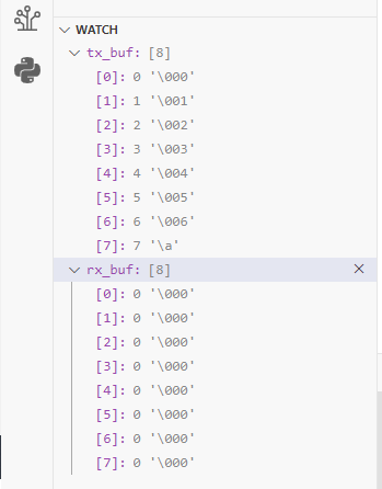
    I need to send data from nRF7002 to external CPU(STM32) use UART protocol, for HW nRF7002 P0.20 connect STM32 RX and RF7002 P0.22 connect STM32 TX, I try to use exercise to modify send 8 bytes data and recieved from STM32 8 bytes data, there is no any data recieved data from STM32 and nRF7002, isn't I miss some config for this flow?below is my device three overlay and code, please give suggestion for this, Thanks.

&uart0_default {
	group1 {
		psels = <NRF_PSEL(UART_TX, 0, 20)>, <NRF_PSEL(UART_RTS, 0, 19)>;
	};
};

&uart0_sleep {
	group1 {
		psels = <NRF_PSEL(UART_TX, 0, 20)>,
				<NRF_PSEL(UART_RX, 0, 22)>,
				<NRF_PSEL(UART_RTS, 0, 19)>,
				<NRF_PSEL(UART_CTS, 0, 21)>;
	};
};
&uart0 {
	status = "okay";
	current-speed = <115200>;
	pinctrl-0 = <&uart0_default>;
	pinctrl-1 = <&uart0_sleep>;
	pinctrl-names = "default", "sleep";
};

#define RECEIVE_BUFF_SIZE 8
const struct device *uart= DEVICE_DT_GET(DT_NODELABEL(uart0));
static uint8_t tx_buf[] =   {0x00,0x01,0x02,0x03,0x04,0x05,0x06,0x07};
static uint8_t rx_buf[RECEIVE_BUFF_SIZE] = {0};
int main(void)
{
	int ret;
		if (!device_is_ready(uart)){
		printk("UART device not ready\r\n");
		return 1 ;
	}
	ret = uart_tx(uart, tx_buf, sizeof(tx_buf), SYS_FOREVER_MS);
	if (ret) {
		return 1;
	}
		ret = uart_rx_enable(uart ,rx_buf,sizeof rx_buf,RECEIVE_TIMEOUT);
	if (ret) {
		return 1;
	}
	while (1) {
		k_msleep(SLEEP_TIME_MS);
	}
}

Best Regards

    Tina


Parents
  • Hi

    Okay that makes a lot more sense. Looking at your overlay file the following stood out:

    &uart0_default {
    	group1 {
    		psels = <NRF_PSEL(UART_TX, 0, 20)>, <NRF_PSEL(UART_RTS, 0, 19)>;
    	};
    };

    It seems here you're using the TX and RTS pin for UART pins here, which should be TX and RX if I'm not mistaken, try changing the RTS pin to UART_RX, 0, 22 instead, and see if that helps.

    Best regards,

    Simon

  • Hi Simonr

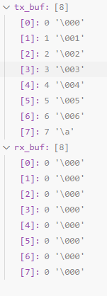
                     I try to modified RTS pin to UART_RX, 0,22 instead, It's doesn't read back any information(below picture), please give any suggestion, Thanks.

    another problem is I need to add one more UART for debug log, isn't can activate at the same time?

    UART0 is for debuging log (print log for debuging)  

    UART1 is for command and small data communicate

    I modify for device tree overlay as below, change uart0 and uart1, for code assign uart1 for device.

    &i2c0 {	status = "disabled";};
    &spi0 {	status = "disabled";};
    &spi2 {	status = "disabled";};
    &i2c1 {	status = "disabled";};
    	
    
    &spi4 {
        compatible = "nordic,nrf-spim";
    	status = "okay";
    	pinctrl-0 = <&spi4_default>;
    	pinctrl-1 = <&spi4_sleep>;
    	pinctrl-names = "default", "sleep";
    	cs-gpios = <&gpio0 11 (GPIO_ACTIVE_LOW | (1 << 8) | (1 << 9))>;
    	stm32f412vgh6: stm32f412vgh6@0 {
    		compatible = "st,stm32f412vgh6";
    		reg = <0>;
    		spi-max-frequency = <DT_FREQ_M(8)>; 
    	};
    
    
        max-frequency = <DT_FREQ_M(8)>;
    };
    
    /* STEP 2.2 - Change the pin configuration */
    &pinctrl {
    	spi4_default: spi4_default {
    		group1 {
    				psels = <NRF_PSEL(SPIM_SCK, 0, 8)>,
    						<NRF_PSEL(SPIM_MOSI, 0, 9)>,
    						<NRF_PSEL(SPIM_MISO, 0, 10)>;
    				nordic,drive-mode = <NRF_DRIVE_H0H1>;		
    		};
    	};
    
    	spi4_sleep: spi4_sleep {
    		group1 {
    				psels = <NRF_PSEL(SPIM_SCK, 0, 8)>,
    						<NRF_PSEL(SPIM_MOSI, 0, 9)>,
    						<NRF_PSEL(SPIM_MISO, 0, 10)>;
    				low-power-enable;
    		};
    	};
    };
    
    &uart0_default {
    	group1 {
    		psels = <NRF_PSEL(UART_TX, 1, 1)>, <NRF_PSEL(UART_RTS, 1, 5)>;
    	};
    
        group2 {
            psels = <NRF_PSEL(UART_RX, 1, 0)>, <NRF_PSEL(UART_CTS, 1, 4)>;
        };
    };
    
    &uart0_sleep {
    	group1 {
    		psels = <NRF_PSEL(UART_TX, 1, 1)>,
    				<NRF_PSEL(UART_RX, 1, 00)>,
    				<NRF_PSEL(UART_RTS, 1, 05)>,
    				<NRF_PSEL(UART_CTS, 1, 04)>;
    	};
    };
    &uart0 {
    	status = "okay";
    	current-speed = <115200>;
    	pinctrl-0 = <&uart0_default>;
    	pinctrl-1 = <&uart0_sleep>;
    	pinctrl-names = "default", "sleep";
    };
    
    &uart1_default {
    	group1 {
    		psels = <NRF_PSEL(UART_TX, 0, 20)>, <NRF_PSEL(UART_RTS, 0, 19)>;
    	};
    	group2 {
            psels = <NRF_PSEL(UART_RX, 0, 22)>, <NRF_PSEL(UART_CTS, 0, 21)>;
        };
    };
    
    &uart1_sleep {
    	group1 {
    		psels = <NRF_PSEL(UART_TX, 0, 20)>,
    				<NRF_PSEL(UART_RX, 0, 22)>,
    				<NRF_PSEL(UART_RTS, 0, 19)>,
    				<NRF_PSEL(UART_CTS, 0, 21)>;
    	};
    };
    &uart1 {
    	status = "okay";
    	current-speed = <115200>;
    	pinctrl-0 = <&uart1_default>;
    	pinctrl-1 = <&uart1_sleep>;
    	pinctrl-names = "default", "sleep";
    };

    #define RECEIVE_BUFF_SIZE 8
    const struct device *uart= DEVICE_DT_GET(DT_NODELABEL(uart1));
    static uint8_t tx_buf[] =   {0x00,0x01,0x02,0x03,0x04,0x05,0x06,0x07};
    static uint8_t rx_buf[RECEIVE_BUFF_SIZE] = {0};
    int main(void)
    {
    	int ret;
    		if (!device_is_ready(uart)){
    		printk("UART device not ready\r\n");
    		return 1 ;
    	}
    	ret = uart_tx(uart, tx_buf, sizeof(tx_buf), SYS_FOREVER_MS);
    	if (ret) {
    		return 1;
    	}
    		ret = uart_rx_enable(uart ,rx_buf,sizeof rx_buf,RECEIVE_TIMEOUT);
    	if (ret) {
    		return 1;
    	}
    	while (1) {
    		k_msleep(SLEEP_TIME_MS);
    	}
    }

    Best Regards

         Tina

Reply
  • Hi Simonr

                     I try to modified RTS pin to UART_RX, 0,22 instead, It's doesn't read back any information(below picture), please give any suggestion, Thanks.

    another problem is I need to add one more UART for debug log, isn't can activate at the same time?

    UART0 is for debuging log (print log for debuging)  

    UART1 is for command and small data communicate

    I modify for device tree overlay as below, change uart0 and uart1, for code assign uart1 for device.

    &i2c0 {	status = "disabled";};
    &spi0 {	status = "disabled";};
    &spi2 {	status = "disabled";};
    &i2c1 {	status = "disabled";};
    	
    
    &spi4 {
        compatible = "nordic,nrf-spim";
    	status = "okay";
    	pinctrl-0 = <&spi4_default>;
    	pinctrl-1 = <&spi4_sleep>;
    	pinctrl-names = "default", "sleep";
    	cs-gpios = <&gpio0 11 (GPIO_ACTIVE_LOW | (1 << 8) | (1 << 9))>;
    	stm32f412vgh6: stm32f412vgh6@0 {
    		compatible = "st,stm32f412vgh6";
    		reg = <0>;
    		spi-max-frequency = <DT_FREQ_M(8)>; 
    	};
    
    
        max-frequency = <DT_FREQ_M(8)>;
    };
    
    /* STEP 2.2 - Change the pin configuration */
    &pinctrl {
    	spi4_default: spi4_default {
    		group1 {
    				psels = <NRF_PSEL(SPIM_SCK, 0, 8)>,
    						<NRF_PSEL(SPIM_MOSI, 0, 9)>,
    						<NRF_PSEL(SPIM_MISO, 0, 10)>;
    				nordic,drive-mode = <NRF_DRIVE_H0H1>;		
    		};
    	};
    
    	spi4_sleep: spi4_sleep {
    		group1 {
    				psels = <NRF_PSEL(SPIM_SCK, 0, 8)>,
    						<NRF_PSEL(SPIM_MOSI, 0, 9)>,
    						<NRF_PSEL(SPIM_MISO, 0, 10)>;
    				low-power-enable;
    		};
    	};
    };
    
    &uart0_default {
    	group1 {
    		psels = <NRF_PSEL(UART_TX, 1, 1)>, <NRF_PSEL(UART_RTS, 1, 5)>;
    	};
    
        group2 {
            psels = <NRF_PSEL(UART_RX, 1, 0)>, <NRF_PSEL(UART_CTS, 1, 4)>;
        };
    };
    
    &uart0_sleep {
    	group1 {
    		psels = <NRF_PSEL(UART_TX, 1, 1)>,
    				<NRF_PSEL(UART_RX, 1, 00)>,
    				<NRF_PSEL(UART_RTS, 1, 05)>,
    				<NRF_PSEL(UART_CTS, 1, 04)>;
    	};
    };
    &uart0 {
    	status = "okay";
    	current-speed = <115200>;
    	pinctrl-0 = <&uart0_default>;
    	pinctrl-1 = <&uart0_sleep>;
    	pinctrl-names = "default", "sleep";
    };
    
    &uart1_default {
    	group1 {
    		psels = <NRF_PSEL(UART_TX, 0, 20)>, <NRF_PSEL(UART_RTS, 0, 19)>;
    	};
    	group2 {
            psels = <NRF_PSEL(UART_RX, 0, 22)>, <NRF_PSEL(UART_CTS, 0, 21)>;
        };
    };
    
    &uart1_sleep {
    	group1 {
    		psels = <NRF_PSEL(UART_TX, 0, 20)>,
    				<NRF_PSEL(UART_RX, 0, 22)>,
    				<NRF_PSEL(UART_RTS, 0, 19)>,
    				<NRF_PSEL(UART_CTS, 0, 21)>;
    	};
    };
    &uart1 {
    	status = "okay";
    	current-speed = <115200>;
    	pinctrl-0 = <&uart1_default>;
    	pinctrl-1 = <&uart1_sleep>;
    	pinctrl-names = "default", "sleep";
    };

    #define RECEIVE_BUFF_SIZE 8
    const struct device *uart= DEVICE_DT_GET(DT_NODELABEL(uart1));
    static uint8_t tx_buf[] =   {0x00,0x01,0x02,0x03,0x04,0x05,0x06,0x07};
    static uint8_t rx_buf[RECEIVE_BUFF_SIZE] = {0};
    int main(void)
    {
    	int ret;
    		if (!device_is_ready(uart)){
    		printk("UART device not ready\r\n");
    		return 1 ;
    	}
    	ret = uart_tx(uart, tx_buf, sizeof(tx_buf), SYS_FOREVER_MS);
    	if (ret) {
    		return 1;
    	}
    		ret = uart_rx_enable(uart ,rx_buf,sizeof rx_buf,RECEIVE_TIMEOUT);
    	if (ret) {
    		return 1;
    	}
    	while (1) {
    		k_msleep(SLEEP_TIME_MS);
    	}
    }

    Best Regards

         Tina

Children
Related