
Hello everyone
I'm the proud owner of a nRF52 Prev. DK and trying to get my project to work. I would like to sample 3 to 5 analog signals using the ADC on the DevKit, followed by sending it to an app, using Ble. The sampled signals would be 3V, 5V if possible. To begin my adventure in this new world, I took the ble proximity example and modified it. At the moment, the ADC samples channel AIN0 and shows the value, as the battery value, on the Nordic toolkit app. Sampling the GND output pin gives me values around 253, the 5V pin gives me values around 60 and the VDD pin (+- 3V) gives me values around 56. I can't seem to figure out from where the nRF is getting those values. I would expect values going from 0 to 1023 (10bit ADC)? The ADC is configurated as a default channel.
Also how should I configurate the ADC (when) using Scan Mode?
UPDATE 14/01/2016
I fixed all the errors and it's compiling perfectly. When I program the code on the nRF, bluetooth doesn't seem to advertise anymore. It seems like the nRF keeps sampling the AIN0 - 2 channels and doesn't come out of it so that the rest of the code can be 'launched'. So the advertising_init(); doesn't get started. Need to find a way how I can let all the channels sample once and then continu the rest of the code.
UPDATE 15/01/2016
Using timer 1 seems to do the trick. Code runs, samples and shows some values on the app.
ble_app_rscs_ADC_Update_15.rar
Question 18/01/2016
Stefan, using the timer ADC code to workaround the Scan Mode issue we init, sample and uninit each channel one by one. Is it still possible to sample the VDD voltage on a different timer? E.g. my compare event timer is set to 2 seconds, so after 2 seconds channel one is getting sampled. Another two seconds later, channel 2 is getting sampled and so on. Let's say I want to sample my VDD every 10 seconds in tandem with the 'two second sampler', is this still possible with this workaround? The only option I see is to config a 4th channel which samples the VDD when 'm_adc_channel_enabled == 3'.
Answer
The safest and easiest way is to implement a 4th channel to sample the Vdd.
Question 26/01/2016
When I run the ADC sample code, implemented in the ble_app_rscs, it seems that the measurement_timeout_handler doesn't get activated anymore. Because of this, my ADC-values aren't getting updated on my smartphone app. When I use the simulated values in my code, the app does get updated. Can this be due to the usage of timer 1 and bluetooth using timer 0 ?
Question 8/02/2016
I changed to code of the saadc_sample_from_three_pins - timer mode application so that the buffer holds 10 measurements and prints the average output. The only disadvantage I experience now is that the printing of the code through UART is very slow. Can this be boosted?
At the moment I use 10 ms to compare every event, for 25 samples in buffer. Aren't these 'extreme' values?
Question 01/04/2016
First of all, thank you or the extra sampling code examples. I took a look at them and for my purpose, using 'oversample' seems to be good enough. Everything runs like I want it to, except the 'timing'.
My code has 3 timers running (and more)
-
Battery (10000ms). After 10 seconds the battery handler will be called and will send the new sampled battery value using: ble_bas_battery_level_update;
-
SampleUpdate (5000ms) This handler will send all te current values of the sensors to my app;
-
SampleTimer (125ms with OVERSAMPLE_8X). After 1000 ms, a channel gets sampled and stored in a variable. 1000ms later, the next channel, ...
What I would expect now is that each time the SampleUpdate timer expires, my values in my application are getting updated. But this happens way faster. If I look at the timestamp in my database, I get the next picture:
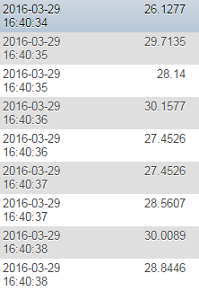
The timestamp gets 'calculated' each time my application recieves an update so this means the Nordic sends the data faster than 5000ms.
Could I have missed something in the bluetooth settings? Or maybe a timers issue?
UPDATE Question 01/04/2016
I somehow seem to have fixed the problem. While I was debugging each part of the code the problem suddenly disappeared.
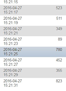
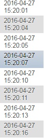
One thing I noticed is that when I choose 125ms as sampling timer, the timing sometimes seems to be out of sync. The database shows me timestamps like these:
When I take 250 ms as SamplingTimer, the problem is solved. Which will do for this application!
Kind regards and thank you for all the help,
Legend
