
I searched for existing forum posts but couldn't find anyone asking this
Why doesn't the dongle use the inverted F antenna?
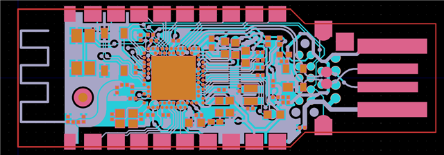
The dongle looks like this
The inverted F looks like this.
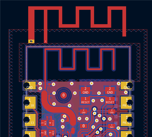
I thought the loop to ground added inductance, which helped the antenna gain.
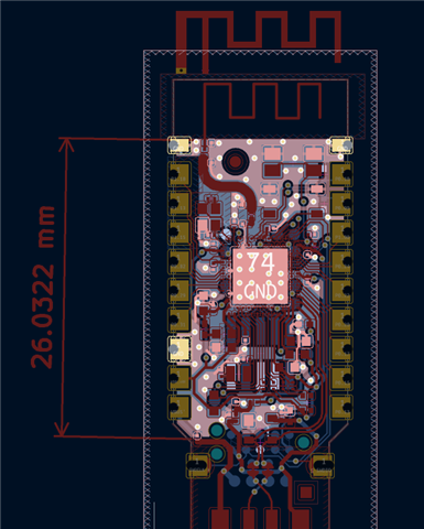
Also, the GND plane seems to be only 26mm, whereas I expected it to be at least 31.25mm (lambda/4)
Thanks for your help,
Kind regards,
-Jason

