Hello Nordic Official! I am currently doing the PCB design of NRF52840 based on your datasheet, but I have some questions.
The manual I refer to is this: [ https://infocenter.nordicsemi.com/pdf/nRF52840_PS_v1.8.pdf ], page 602, "7.3.7 Circuit configuration no. 7 for QIAA aQFN73".
Here are some of my questions:
1. Is the following understanding correct?
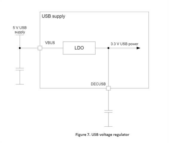
Pin VDDH (Y2) supplies power to the chip. When Pin VBUS (AD2) is powered on, it only tells the chip that a USB Host is now connected. Pin VBUS does not supply power to the chip. If you are making the nRF52840 core board and there is only 5V power supply on the PCB, Pin VDDH must always be connected to 5V, and Pin VBUS can be left unconnected.
2. For newer chips, C9 (820pF) is not needed. Should Pin N24 be changed to N.C., or C9 should be changed to N.C.?
3. Can the pull-up power supply of Pin nRESET use the 3V voltage output by nRF_VDD? When the system is just started, is it possible that the register controlling the nRF_VDD output has not been initialized, resulting in unexpected reset behavior?