
I'm trying to modify this bit-banging ws2812 gpio Zephy driver to run on an nrf9160 board. The problem is I can't mange to get consistent pulse timing using assembly instructions, especially at the beginning of the transfer.
I know there have been similar questions, (i.e. nRF9160 ws2812 GPIO driver - only works when debug optimisations are off) but I haven't been able to find a solution that sticks with bit-banging.
I need to control 5 to 10 independent pixel "strips" that are NOT daisy-chained together, so using an SPI or PWM driver won't work for my case. At least not without dynamic pin-control/pin-muxing at runtime, which isn't currently supported in zephyr.
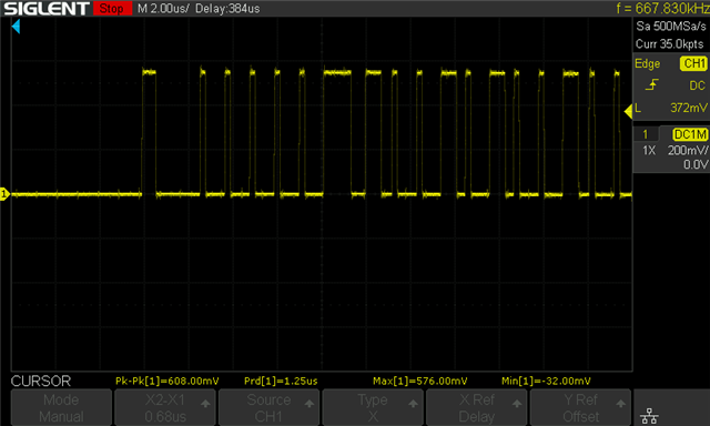
You can see that the first pulse has about double the width (time) as the second pulse, even though they should be the same (a zero bit). The 7th and 8th pulse should also be the same (a one bit).
This is code I've been messing with/debugging:
/*
 * Copyright (c) 2018 Intel Corporation
 * Copyright (c) 2019 Nordic Semiconductor ASA
 * Copyright (c) 2021 Seagate Technology LLC
 *
 * SPDX-License-Identifier: Apache-2.0
 */
#define DT_DRV_COMPAT worldsemi_ws2812_gpio

#include <zephyr/drivers/led_strip.h>

#include <string.h>

#define LOG_LEVEL CONFIG_LED_STRIP_LOG_LEVEL
#include <zephyr/logging/log.h>
LOG_MODULE_REGISTER(ws2812_gpio);

#include <zephyr/kernel.h>
#include <soc.h>
#include <zephyr/drivers/gpio.h>
#include <zephyr/device.h>
#include <zephyr/drivers/clock_control.h>
#include <zephyr/drivers/clock_control/nrf_clock_control.h>
#include <zephyr/dt-bindings/led/led.h>

struct ws2812_gpio_cfg {
	struct gpio_dt_spec in_gpio;
	uint8_t num_colors;
	const uint8_t *color_mapping;
};

/*
 * T1H: 1 bit high pulse delay: 12 cycles == .75 usec
 * T0H: 0 bit high pulse delay: 4 cycles == .25 usec
 * TxL: inter-bit low pulse delay: 8 cycles == .5 usec
 *
 * We can't use k_busy_wait() here: its argument is in microseconds,
 * and we need roughly .05 microsecond resolution.
 */
#define DELAY_T1H                                                                                  \
	"nop\nnop\nnop\nnop\nnop\nnop\nnop\nnop\nnop\nnop\n"                                       \
	"nop\nnop\nnop\nnop\nnop\nnop\nnop\nnop\nnop\nnop\n"                                       \
	"nop\nnop\nnop\nnop\nnop\nnop\nnop\nnop\nnop\nnop\n"                                       \
	"nop\nnop\nnop\nnop\nnop\nnop\nnop\nnop\nnop\nnop\n"                                       \
	"nop\nnop\nnop\nnop\nnop\nnop\nnop\nnop\nnop\nnop\n"                                       \
	"nop\nnop\nnop\nnop\nnop\nnop\nnop\nnop\nnop\nnop\n"                                       \
	"nop\nnop\nnop\nnop\nnop\nnop\nnop\nnop\nnop\nnop\n"                                       \
	"nop\nnop\nnop\nnop\nnop\nnop\nnop\nnop\nnop\nnop\n"                                       \
	"nop\nnop\nnop\nnop\nnop\nnop\nnop\nnop\nnop\nnop\n"

#define DELAY_T0H                                                                                  \
	"nop\nnop\nnop\nnop\nnop\nnop\nnop\nnop\nnop\nnop\n"                                       \
	"nop\nnop\nnop\nnop\nnop\nnop\nnop\nnop\nnop\nnop\n"                                       \
	"nop\nnop\nnop\nnop\nnop\nnop\nnop\nnop\nnop\nnop\n"

/*
 * GPIO set/clear.
 *
 * We should be able to make this portable using the results of
 * https://github.com/zephyrproject-rtos/zephyr/issues/11917.
 *
 * We already have the GPIO device stashed in ws2812_gpio_config, so
 * this driver can be used as a test case for the optimized API.
 *
 * Per Arm docs, both Rd and Rn must be r0-r7, so we use the "l"
 * constraint in the below assembly.
 */
#define SET_HIGH "str %[p], [%[s], #0]\n" /* OUTSET = BIT(LED_PIN) */
#define SET_LOW  "str %[p], [%[c], #0]\n" /* OUTCLR = BIT(LED_PIN) */

/* Send out a 1 bit's pulse */
#define ONE_BIT(set, clear, pin)                                                                   \
	__asm volatile(SET_HIGH DELAY_T1H SET_LOW DELAY_T0H ::[s] "l"(set), [c] "l"(clear),        \
		       [p] "l"(pin));

/* Send out a 0 bit's pulse */
#define ZERO_BIT(set, clear, pin)                                                                  \
	__asm volatile(SET_HIGH DELAY_T0H SET_LOW DELAY_T1H ::[s] "l"(set), [c] "l"(clear),        \
		       [p] "l"(pin));

/*
 * Latch current color values on strip and reset its state machines.
 */
static inline void ws2812_led_strip_reset_delay(uint16_t delay)
{
	k_usleep(delay);
}

static int send_buf(const struct device *dev, uint8_t *buf, size_t len)
{
	const struct ws2812_gpio_cfg *config = dev->config;
	volatile uint32_t *set = (uint32_t *)&NRF_P0->OUTSET;
	volatile uint32_t *clear = (uint32_t *)&NRF_P0->OUTCLR;
	const uint32_t pin = BIT(config->in_gpio.pin);
	unsigned int key;

	struct onoff_manager *mgr = z_nrf_clock_control_get_onoff(CLOCK_CONTROL_NRF_SUBSYS_HF);
	struct onoff_client cli;
	int rc;

	sys_notify_init_spinwait(&cli.notify);
	rc = onoff_request(mgr, &cli);
	if (rc < 0) {
		return rc;
	}

	while (sys_notify_fetch_result(&cli.notify, &rc)) {
		/* pend until clock is up and running */
	}

	size_t i;
	int j = 0;
	key = irq_lock();

	while (len--) {
		/*
		 * Generate signal out of the bits, MSbit first.
		 *
		 * Accumulator maintenance and branching mean the
		 * inter-bit time will be longer than TxL, but the
		 * wp.josh.com blog post says we have at least 5 usec
		 * of slack time between bits before we risk the
		 * signal getting latched, so this will be fine as
		 * long as the compiler does something minimally
		 * reasonable.
		 */
		for (i = 0; i < 8; i++) {
			if (0b10000000 & (*(buf + j) << i)) {
				ONE_BIT(set, clear, pin);
			} else {
				ZERO_BIT(set, clear, pin);
			}
		}
		j++;
	}

	irq_unlock(key);

	rc = onoff_release(mgr);
	// LOG_DBG("onoff_release rc: %i", rc);
	/* Returns non-negative value on success. Cap to 0 as API states. */
	rc = MIN(rc, 0);

	return rc;
}

static int ws2812_gpio_update_rgb(const struct device *dev,
				  struct led_rgb *pixels,
				  size_t num_pixels)
{
	const struct ws2812_gpio_cfg *config = dev->config;
	uint8_t *ptr = (uint8_t *)pixels;
	size_t i;
	int rc;

	/* Convert from RGB to on-wire format (e.g. GRB, GRBW, RGB, etc) */
	for (i = 0; i < num_pixels; i++) {
		uint8_t j;

		for (j = 0; j < config->num_colors; j++) {
			switch (config->color_mapping[j]) {
			/* White channel is not supported by LED strip API. */
			case LED_COLOR_ID_WHITE:
				*ptr++ = 0;
				break;
			case LED_COLOR_ID_RED:
				*ptr++ = pixels[i].r;
				break;
			case LED_COLOR_ID_GREEN:
				*ptr++ = pixels[i].g;
				break;
			case LED_COLOR_ID_BLUE:
				*ptr++ = pixels[i].b;
				break;
			default:
				return -EINVAL;
			}
		}
	}

	rc = send_buf(dev, (uint8_t *)pixels, num_pixels * config->num_colors);

	ws2812_led_strip_reset_delay(300);
	return rc;
}

static int ws2812_gpio_update_channels(const struct device *dev,
				       uint8_t *channels,
				       size_t num_channels)
{
	LOG_ERR("update_channels not implemented");
	return -ENOTSUP;
}

static const struct led_strip_driver_api ws2812_gpio_api = {
	.update_rgb = ws2812_gpio_update_rgb,
	.update_channels = ws2812_gpio_update_channels,
};

/*
 * Retrieve the channel to color mapping (e.g. RGB, BGR, GRB, ...) from the
 * "color-mapping" DT property.
 */
#define WS2812_COLOR_MAPPING(idx)					\
static const uint8_t ws2812_gpio_##idx##_color_mapping[] =		\
	DT_INST_PROP(idx, color_mapping)

#define WS2812_NUM_COLORS(idx) (DT_INST_PROP_LEN(idx, color_mapping))

/*
 * The inline assembly above is designed to work on nRF51 devices with
 * the 16 MHz clock enabled.
 *
 * TODO: try to make this portable, or at least port to more devices.
 */

#define WS2812_GPIO_DEVICE(idx)					\
									\
	static int ws2812_gpio_##idx##_init(const struct device *dev)	\
	{								\
		const struct ws2812_gpio_cfg *cfg = dev->config;	\
		uint8_t i;						\
									\
		if (!gpio_is_ready_dt(&cfg->in_gpio)) {		\
			LOG_ERR("GPIO device not ready");		\
			return -ENODEV;					\
		}							\
									\
		for (i = 0; i < cfg->num_colors; i++) {			\
			switch (cfg->color_mapping[i]) {		\
			case LED_COLOR_ID_WHITE:			\
			case LED_COLOR_ID_RED:				\
			case LED_COLOR_ID_GREEN:			\
			case LED_COLOR_ID_BLUE:				\
				break;					\
			default:					\
				LOG_ERR("%s: invalid channel to color mapping." \
					" Check the color-mapping DT property",	\
					dev->name);			\
				return -EINVAL;				\
			}						\
		}							\
									\
		return gpio_pin_configure_dt(&cfg->in_gpio, GPIO_OUTPUT); \
	}								\
									\
	WS2812_COLOR_MAPPING(idx);					\
									\
	static const struct ws2812_gpio_cfg ws2812_gpio_##idx##_cfg = { \
		.in_gpio = GPIO_DT_SPEC_INST_GET(idx, in_gpios),	\
		.num_colors = WS2812_NUM_COLORS(idx),			\
		.color_mapping = ws2812_gpio_##idx##_color_mapping,	\
	};								\
									\
	DEVICE_DT_INST_DEFINE(idx,					\
			    ws2812_gpio_##idx##_init,			\
			    NULL,					\
			    NULL,					\
			    &ws2812_gpio_##idx##_cfg, POST_KERNEL,	\
			    CONFIG_LED_STRIP_INIT_PRIORITY,		\
			    &ws2812_gpio_api);

DT_INST_FOREACH_STATUS_OKAY(WS2812_GPIO_DEVICE)
I believe the nrf9160 uses the "RTC" for systick which isn't super accurate. Or maybe the delay is from accumulator maintenance and branching as one of the code comments suggest?
Other posts and drivers like the uart_nrf_sw_lpuart seem to suggest that I should be using the `gpiote` instead of the `gpio` driver, but I haven't used that driver in the past and I'm not sure how I'd set it up with a clock as a trigger.
Is there a way I can use a more accurate clock source or remove the delay from the assembly execution?
Thanks!

