Unable to interface PCF8574 with nr53DK.

Hello!

I'm following the NRF Academy Fundamentals course and I am facing an issue with I2C devices.

I have an STM32 board with HAL code (Non-Zephyr) and I am able to interface the PCF8574 IC successfully. 

This sensor board has 10k pull-up resistors attached to SDC and SCL. The pull-up voltage is 5V.

When I tried to run the solution provided for Exercise6-1, I had two Issues:

  • Bus fault: I solved it by switching NCS from v2.6.0 to v2.5.3
  • I2C error: [2024-05-09 17:49:25] [00:04:59.580,963] <err> i2c_nrfx_twim: Error 0x0BAE0001 occurred for message 0
    [2024-05-09 17:49:25] Failed to write to I2C device address 40 at Reg. aabb, -5


int main(void)
{

	int ret;

	printk("Booting up I2C app\r\n");

/* STEP 7 - Retrieve the API-specific device structure and make sure that the device is ready to use  */
	static const struct i2c_dt_spec dev_i2c = I2C_DT_SPEC_GET(I2C_NODE);
	if (!device_is_ready(dev_i2c.bus)) {
		printk("I2C bus %s is not ready!\n\r",dev_i2c.bus->name);
		return -1;
	}


	uint16_t data = 0xAABB;


	while (1) {
			ret = i2c_write_dt(&dev_i2c, &data, 2);
		if(ret != 0){
			printk("Failed to write to I2C device address %x at Reg. %x, %d \r\n", dev_i2c.addr, data, ret);
	}
		k_msleep(SLEEP_TIME_MS);
	}
}

The main code is pretty simple, it checks if the device is ready and sends the data

STM32 Hal config: 

  hi2c1.Instance = I2C1;
  hi2c1.Init.Timing = 0x60404E72;
  hi2c1.Init.OwnAddress1 = 0;
  hi2c1.Init.AddressingMode = I2C_ADDRESSINGMODE_7BIT;
  hi2c1.Init.DualAddressMode = I2C_DUALADDRESS_DISABLE;
  hi2c1.Init.OwnAddress2 = 0;
  hi2c1.Init.OwnAddress2Masks = I2C_OA2_NOMASK;
  hi2c1.Init.GeneralCallMode = I2C_GENERALCALL_DISABLE;
  hi2c1.Init.NoStretchMode = I2C_NOSTRETCH_DISABLE;
  
    GPIO_InitStruct.Pin = GPIO_PIN_6|GPIO_PIN_7;
    GPIO_InitStruct.Mode = GPIO_MODE_AF_OD;
    GPIO_InitStruct.Pull = GPIO_PULLUP;
    GPIO_InitStruct.Speed = GPIO_SPEED_FREQ_LOW;
    GPIO_InitStruct.Alternate = GPIO_AF4_I2C1;
    HAL_GPIO_Init(GPIOB, &GPIO_InitStruct);

I tried to set pull-up config in the device tree, and the results are the same. The I2C device address is 0x40.

Not sure what could be going wrong. Can someone please look into it?

  • Hi Navin

    Could you post your devicetree and your prj.conf?

    Nb. We are a bit shorter staffed than usual at devzone due to today being a squeeze day in Norway (Friday after a national holiday) so the response time might be longer then usual. 

    Regards

    Runar

  • Hi Runar,

    Thank you for the response!

    Here is prj.conf

    #
    # Copyright (c) 2016 Intel Corporation
    #
    # SPDX-License-Identifier: Apache-2.0
    #
    
    # STEP 2 - Enable the I2C driver
    CONFIG_I2C=y
    # STEP 4.2 - Enable floating point format specifiers
    CONFIG_CBPRINTF_FP_SUPPORT=y
    CONFIG_LOG=y

    And here is the DTS overlay:

    &i2c1 {
    
        mysensor: mysensor@40{
            compatible = "i2c-device";
            status = "okay";
            reg = < 0x40 >;
        };
    };

    Also, please find the final zephyr.dts

    6116.zephyr.dts

    Best regards,

    Navin

  • If you have a look at the device binding which you can find here, you will see that you are missing a few field 

    It should look something similar to this

    &i2c {
      status = "okay";
      pcf8574: pcf857x@20 {
          compatible = "nxp,pcf857x";
          status = "okay";
          reg = <0x20>;
          gpio-controller;
          #gpio-cells = <2>;
          ngpios = <8>;
      };
    
    
    };

    If you are using the newest version NCS the Kconfig should be CONFIG_GPIO_PCF857X=y 

    Regards

    Runar

  • Hi Runar,

    Thanks for response! 

    I found out what was wrong with my code. The address is supposed to be 0x20 and not 0x40, as it a 7-bit address. ST HAL API expects an 8-bit left shifted value, which confused me.

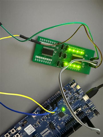
    Here is an alternating pattern for: 

    uint16_t data = 0xAA55;

    It works with the same DT binding I initially provided with the default arduino pins (P1.03 and P1.02). 

    &i2c1 {

        mysensor: mysensor@20{
          compatible = "i2c-device";
          status = "okay";
          reg = < 0x20 >;
       };
    };

    Thanks again for pointing out the issue, it helped in figuring out the solution.

    Best regards,

    Navin

Related