Issue with IMU Sensor (LSM6DSV16X) Sample Rate in Sensor Hub Mode

I am using an IMU sensor in sensor hub mode (LSM6DSV16X, LIS2MDL) with the FIFO interrupt interval set at 30 Hz. The data is sent over BLE. It works perfectly when using RTT, but when I disable debug mode, the sample rate drops to around 1 Hz.

Could someone please help me resolve this issue?

Thank you.

Parents
  • Thank you for your reply. When the IMU's FIFO is full, an interrupt will occur on the interrupt pin. The interrupt rate will decrease to 1 Hz as if something changes or is missed when I disable the RTT configuration.

  • So what triggers the IMU readings in the first place? Do you have a timer set up at 30Hz or something?

    What HW are you running this on? nRF5340DK? Or do you have a custom board?

  • Please find attached your requested file. If you run and connect to the BLE central, you can see the data rate difference on the BLE central's output on the terminal when RTT is connected and disconnected.

    Thank you,

    Saeed

    nrf5340_imu_adc_led_ble_Apr5.zip

  • Hello,

    The project that you sent doesn't have RTT logging enabled. Are you sure that you are seeing the issue with that exact application, without any modifications? It also seems like IMU_SIMULATION was set to 0. Either way, closing the RTT viewer didn't impact the rate at which the notifications are coming in, as you can tell from the timestamps here, from after closing the RTT window. 

  • I apologize for the confusion. The IMU_simulation value should be set to 1. This is the only change that needs to be made, and I believe you have already implemented it. For more clarity, I have recorded my screen to ensure we are on the same page.

    I appreciate your time and help.

    Best,

    Saeed

  • Please share sensor data and individual firmware. Here i am getting the ADC data only. I need lsm6dsv16x data. 

  • I think the problem is not from IMU side. anyway, the firmware already contains the IMU lib

Reply Children
  • It is perplexing to find the sensor data. I hope you are the guide for me to fix the problem.

  • Could you please share hardware connection over the I2C.

  • SaeedZadeh said:
    I apologize for the confusion. The IMU_simulation value should be set to 1. This is the only change that needs to be made,

    RTT logging was also disabled. This makes me think there may be other changes as well.

    Regarding the video. Are you saying that the text in the UART terminal on the left is increasing when you enable RTT? It didn't look like it. 

    The amount of logs on RTT is higher, yes. Is that what you are saying? That doesn't mean that the sampling is higher. That just depends what you are logging. Also, RTT has a higher throughput than UART. 

    I think the video clarified that I am not looking at the same thing as you, so I need some more details on what you mean the issue is.

    BR,
    Edvin

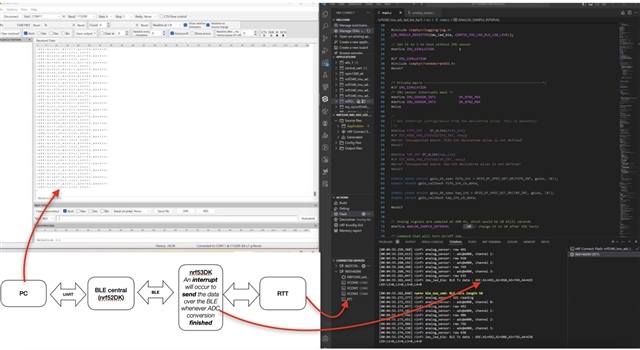
  • Thank you for your attention, Edvin! To clarify, please take a look at the system's block diagram. There are two DK boards.

    Also, to be more intuitive, I'm trying to toggle a pin in a while(1) loop every 20ms. I've noticed that the timing significantly increases when the RTT is not connected but normalizes once I connect the RTT. I've attached a video for your reference.

    	while (1) {
    
    		ret = gpio_pin_toggle_dt(&signal_pin);
    		if(ret < 0){
    			return 0;
    		};
    		k_msleep(20);
    		//k_sleep(K_FOREVER);
    	}

    Best,

Related