Hi all!
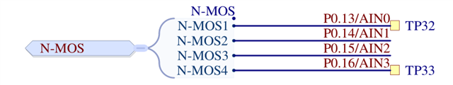
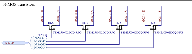
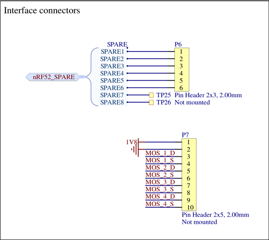
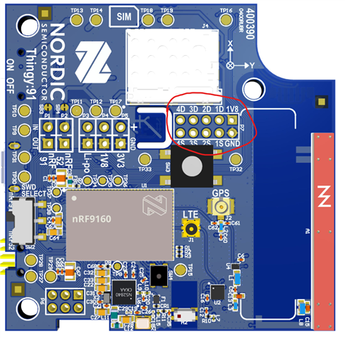
Hopefully this doesn't come off as too much of an ignorant question, but I'm having a hard time understanding the pinout of the Thingy 91 since I can't map where each pin on the table, provided by the hardware files, is to the physical board. If someone could provide some insight that would be greatly appreciated. I want to be able to connect a status led and switch to two GPIO pins that I can control when I transmit sensor data over to another cellular device. I assume I would connect these components to the sink/drain MOSFET pins provided unless I've understood the board layout incorrectly.
If you've seen a previous post I've made, I think I've found a solution to my external power situation with an USB A adaptor board. The one I found is the BOB-12700 and the board has the D+/D- pins and I'm not sure where these data line pins would be connected to on the Thingy. Would also appreciate some advice on how to rectify that situation or if I leave those pins not connected(I would assume not since that is how the USB port knows when to drive 5V)?
Thank you for your help!!