ST7789V Display

Hi all,

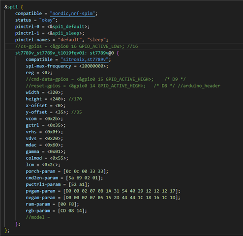
I have been successfully using an Adafruit 1.9" 170x320 ST7789 display, but when I switch to the Waveshare 2" 240x320 ST7789V display it doesn't work. I'm wondering if I'm forgetting to do something in devicetree but nothing obvious sticks out? Has anyone had a problem similar to this?

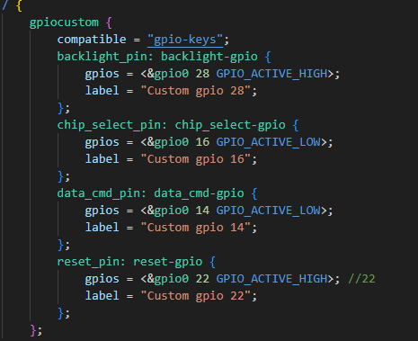
Any help would be appreciated. I attached part of my devicetree below.

  • I think you should not mark off cs-gpios, cmd-data-gpios, and reset-gpios.

    When the display device is ready, you need to call blanking_off() to display it correctly.

    Please refer to the example code below.

    static const struct device    *display_dev;
    static const struct display_driver_api *st7789v_api;
    
    static void    wl_display_thread(void *p1, void *p2, void *p3)
    {
        int    err;
    
    
        display_dev = DEVICE_DT_GET(DT_CHOSEN(zephyr_display));
    
        LOG_INF("wl_display_thread");
    
        if(!device_is_ready(display_dev))
        {
            LOG_ERR("Device not ready, aborting test");
            return 0;
        }
    
        st7789v_api = display_dev->api;
        st7789v_api->blanking_off(display_dev);
       
        setup_ui(&guider_ui);
        events_init(&guider_ui);
        custom_init(&guider_ui);
    
        while (1)
        {
            lv_task_handler();
            k_sleep(K_MSEC(5));
        }
    }

  • I'm using Adafruit GFX library to control the pins. They are defined below. I'm also not using the Zephyr display driver. According to my oscilloscope, the signal is identical to each display so I'm thinking that the ST7789V is configured to receive data differently, hence why I thought it might be related to device tree.

  • Here is my device tree.overlay , perhaps you can compare the differences between the two. Refer to the ST7789V specification to find the differences.

    &arduino_spi {
    	status = "okay";
    	cs-gpios = <&arduino_header 16 GPIO_ACTIVE_LOW>;	/* D10 */
    
    	st7789v_st7789v_waveshare_240x240: st7789v@0 {
    		compatible = "sitronix,st7789v";
    		spi-max-frequency = <20000000>;
    		reg = <0>;
    		cmd-data-gpios = <&arduino_header 15 GPIO_ACTIVE_LOW>;	/* D9 */
    		reset-gpios = <&arduino_header 14 GPIO_ACTIVE_LOW>;	/* D8 */
    		width = <240>;
    		height = <240>;
    		x-offset = <0>;
    		y-offset = <0>;
    		vcom = <0x19>;
    		gctrl = <0x35>;
    		vrhs = <0x12>;
    		vdvs = <0x20>;
    		mdac = <0x00>;
    		gamma = <0x01>;
    		colmod = <0x05>;
    		lcm = <0x2c>;
    		porch-param = [0c 0c 00 33 33];
    		cmd2en-param = [5a 69 02 01];
    		pwctrl1-param = [a4 a1];
    		pvgam-param = [D0 04 0D 11 13 2B 3F 54 4C 18 0D 0B 1F 23];
    		nvgam-param = [D0 04 0C 11 13 2C 3F 44 51 2F 1F 1F 20 23];
    		ram-param = [00 F0];
    		rgb-param = [CD 08 14];
    	};
    };

  • It didn't seem to help upon initial testing, but I will experiment some more on Monday. My display is 240x320 but messing with the width and height didn't help. I might be missing something else. Really appreciate your responses!

  • The problem was that the logic pins were running on 1.8v while the display was power with 3.3v.

Related