HI,
I am building an IoT product using NRF58233 ICs.
In which I use 3 PWM channels and 3 ADC channels.
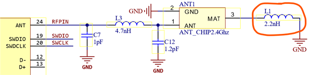
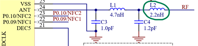
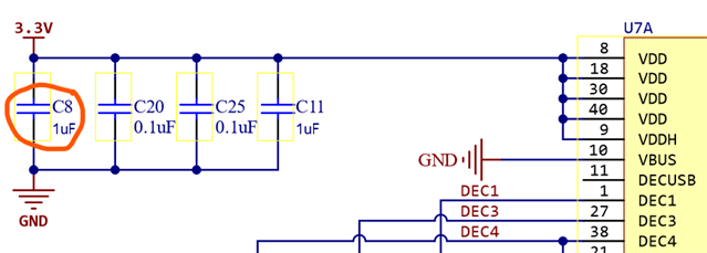
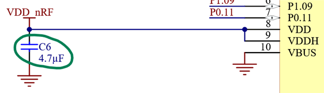
You can review the principle I attached to make sure nothing went wrong. Thanks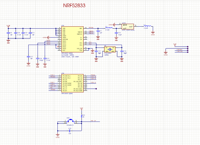
HI,
I am building an IoT product using NRF58233 ICs.
In which I use 3 PWM channels and 3 ADC channels.
You can review the principle I attached to make sure nothing went wrong. Thanks