nRF52832 BLE UUID value incorrect

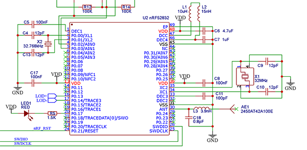
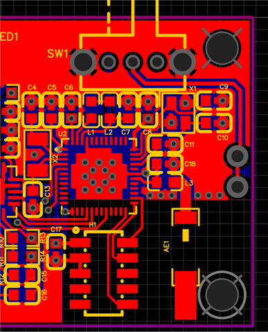
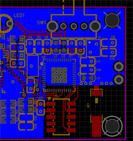
I don't know if this is a hardware or a software problem. My nRF52832 code runs correctly on a PCA10040 development board (UUID = E9:4A:AF:04:D2:16). My custom hardware advertises correctly but the UUID is incorrect (C9:7C:A5:8B:19:EB). The 32MHz xtal is +/-10ppm @ 12pF load. I have tried everything that I can think of including a PCB layout using a 50 ohm SMA antenna, same problem.

Parents
  • Hi,


    My nRF52832 code runs correctly on a PCA10040 development board (UUID = E9:4A:AF:04:D2:16). My custom hardware advertises correctly but the UUID is incorrect (C9:7C:A5:8B:19:EB).

    It is to be expected that the MAC address differs from one device to another. By default, the mac address used is loaded from the FICR DEVICEADDR register, which is uniquely generated for each device.

    The 32MHz xtal is +/-10ppm @ 12pF load

    Does your XTAL have a "Cl" parameter of 12 pF?


    If yes, then the loading caps should be ~20 pF.

    C = 2*CL - Cpin

    Cpin = 4pF


    C=2*12-4=20 pF.


    Your layout seems to differ from the reference design:

    * Please note how the reference layout aligns the first inductor on the ANT pin: https://docs.nordicsemi.com/bundle/ps_nrf52832/page/ref_circuitry.html#d941e1505

    * Your chip antenna lacks antenna-tuner components. Usually 3 components, either a pi-network or a T-network.

    * The components L3 and C18 seems to be 0603 - we recommend that you use 0402 component size.


    Kind regards,

    Håkon

Reply
  • Hi,


    My nRF52832 code runs correctly on a PCA10040 development board (UUID = E9:4A:AF:04:D2:16). My custom hardware advertises correctly but the UUID is incorrect (C9:7C:A5:8B:19:EB).

    It is to be expected that the MAC address differs from one device to another. By default, the mac address used is loaded from the FICR DEVICEADDR register, which is uniquely generated for each device.

    The 32MHz xtal is +/-10ppm @ 12pF load

    Does your XTAL have a "Cl" parameter of 12 pF?


    If yes, then the loading caps should be ~20 pF.

    C = 2*CL - Cpin

    Cpin = 4pF


    C=2*12-4=20 pF.


    Your layout seems to differ from the reference design:

    * Please note how the reference layout aligns the first inductor on the ANT pin: https://docs.nordicsemi.com/bundle/ps_nrf52832/page/ref_circuitry.html#d941e1505

    * Your chip antenna lacks antenna-tuner components. Usually 3 components, either a pi-network or a T-network.

    * The components L3 and C18 seems to be 0603 - we recommend that you use 0402 component size.


    Kind regards,

    Håkon

Children
No Data
Related