Recover from a brown-out reset

Hi,

I encountered an issue from my custom board who are using a nrf52832.

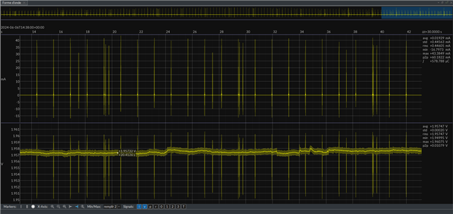
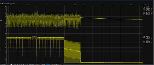
When i place my board in very cold temperature environment (around -35°C), sometimes the voltage drop below VBor, that put my device in reset state.

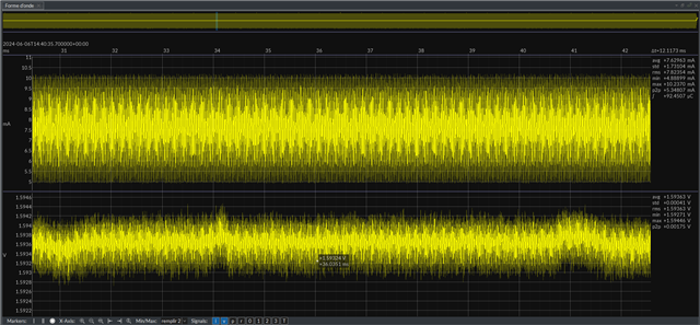
My issue are the voltage could stay below Vbor during long time (>15min), and the consumption is around 1-2mA against 20uA in running state. That reduce considerably my life time of my device.

Is this consumption normal (i don't found any information about this) ? Is there is a way to reduce it ?

I see some devzone that explain the best way is to use the POF in order to put the system-off mode before brown-out are detected. My issue are how to wake up the device from the system-off when the voltage are not critical ? In other way, how to wake up the device without human action ?

For information the battery use is a CR2450 with operating temperature -40 to 85 °C.

Thanks,

Best Regards,

Julien

Parents
  • Hello Julien,

    After discussing this with my team, we figured that if the battery can't deliver enough voltage, the nRF can end up in a reset cycle, where it browns out and turns off, which will cause it to stop drawing power, causing the battery voltage to increase, which will then start up the nRF, which will draw power again, drawing down the voltage of the battery and rinse and repeat.

    Have you tried doing this in a controlled environment, measuring the actual voltage of the battery?

    What you can try to do is to set up the POF to put the device in system off. In order to bring the device back, you can try to use the LPCOMP, which will be able to wake up the nRF from system off, generating an event when the comparator detects a voltage above a certain level.

    This may not work 100%, because if the voltage drops sufficiently, it will start if the voltage increases again, which will be a power on reset, and there is no way to prevent that. But you can give it a go, and see if it makes the situation any better. 

    For information the battery use is a CR2450 with operating temperature -40 to 85 °C.

    I don't know what battery it has, but the issue may be that the battery's internal resistance is too high when the temperature drops, meaning the voltage also drops when drawing power. 

    Best regards,
    Edvin

  • Hello,

    Thanks for the answer, i understand the process, but i'm not sure that i can use the LPCOMP.

    Indeed, all my analalog input (AIN0 to AIN7) are left unconnected on my device, and regarding the LPCOMP page https://infocenter.nordicsemi.com/index.jsp?topic=%2Fcom.nordic.infocenter.nrf52832.ps.v1.1%2Flpcomp.html we cannot use Vdd as Vin+ input. 

    Is there something I'm missing or am i stuck ?

    And what do you mean "in a controlled environment"  ? Do you mean with no peak current and ambiant temperature ?

    Best Regards,

    Julien

  • Julien said:
    Is there something I'm missing or am i stuck ?

    Ah, you are correct. I thought you could (it is possible to use VDD as an input on the SAADC, but not on the LPCOMP). This means you would need to connect one of the AIN pins to the battery, so if it is too late to edit the design, then that doesn't seem possible. 

    Julien said:

    And what do you mean "in a controlled environment"  ? Do you mean with no peak current and ambiant temperature ?

    I mean putting the device in a temperature chamber, and measuring the actual voltage of the battery. Alternatively, set up a power supply that you can control, and check whether you can achieve the same current consumption if you turn down the voltage sufficiently.

    By the way, how do you determine that the current consumption increased to 1-2mA? Do you use a PPK or an oscilloscope or something to measure? In that case, do you have any pictures/screenshots of it?

    Unfortunately, I can't think of any other way of waking up from system off mode, apart from a pin interrupt, which would require an external source (or a button press). As you can see in the System off mode description, there are very few things that can actually wake up the device from system off. 

    To minimize the issue, are there any power-hungry operations that you are doing on startup? (flash writes?) Alternatively you can try to wait a few seconds before using the radio, if that is acceptable for your application. This way, perhaps it doesn't get stuck in a state where it resets every few ms, but perhaps every few seconds instead. 

    Best regards,

    Edvin

Reply
  • Julien said:
    Is there something I'm missing or am i stuck ?

    Ah, you are correct. I thought you could (it is possible to use VDD as an input on the SAADC, but not on the LPCOMP). This means you would need to connect one of the AIN pins to the battery, so if it is too late to edit the design, then that doesn't seem possible. 

    Julien said:

    And what do you mean "in a controlled environment"  ? Do you mean with no peak current and ambiant temperature ?

    I mean putting the device in a temperature chamber, and measuring the actual voltage of the battery. Alternatively, set up a power supply that you can control, and check whether you can achieve the same current consumption if you turn down the voltage sufficiently.

    By the way, how do you determine that the current consumption increased to 1-2mA? Do you use a PPK or an oscilloscope or something to measure? In that case, do you have any pictures/screenshots of it?

    Unfortunately, I can't think of any other way of waking up from system off mode, apart from a pin interrupt, which would require an external source (or a button press). As you can see in the System off mode description, there are very few things that can actually wake up the device from system off. 

    To minimize the issue, are there any power-hungry operations that you are doing on startup? (flash writes?) Alternatively you can try to wait a few seconds before using the radio, if that is acceptable for your application. This way, perhaps it doesn't get stuck in a state where it resets every few ms, but perhaps every few seconds instead. 

    Best regards,

    Edvin

Children
  • Ah, you are correct. I thought you could (it is possible to use VDD as an input on the SAADC, but not on the LPCOMP). This means you would need to connect one of the AIN pins to the battery, so if it is too late to edit the design, then that doesn't seem possible. 

    Even i could, my VDD is Vbat, so comparator will never triggered. The LPCOMP will not works with the battery. So LPCOMP not seem to be the solution here.

    By the way, how do you determine that the current consumption increased to 1-2mA? Do you use a PPK or an oscilloscope or something to measure? In that case, do you have any pictures/screenshots of it?

    Yes, we use a joulescope, i joined to you picture of standard consumption, and "Vbor" consumption.

    Standard consumption

    Here the standard consumption, around 20 uA

    Vbor consumption

    Here the Vbor consumption around 8mA.

    For this test, i use a power supply and not a battery.

    Regards,

    Julien

  • Two things here, first concerns bulk capacitance, both value and voltage rating if using ceramic caps. Are you able to share the schematic? or at least the battery and supply side, along with any high-current (>1mA) hardware devices.

    The second is in any coin-cell based design the potential high internal impedance of the battery under near end-of-life and extreme low temperatures has to be managed under reset or startup conditions. Typically one would do this by reading the voltage via SAADC or LPCOMP before any other cpu activity takes place (before even system init and applying chip errata workarounds, C++ stuff, etc) preferably in some low-level asm code or in C if compiler inits are quick. The SAADC of course takes cpu power and so is not a preferred solution although it is simple and accurate; however, the actual voltage value is unimportant, the question really is does the voltage stay above some nominal value (say 2.5 volts for the CR2450) for some nominal cpu time (say 1mSec). That is trivial, assuming VDD is different from VBAT, so hardware dependent, in which case  just use a simple CR time constant and see how long it takes to charge C via R until a port pin low level changes to a high level or LPCOMP is triggered. Part of the existing circuit can often be used.

    t = CR * ln(1-(VinH/VBAT)) so if VBAT = VDD this trick won't work as VinH on the nRF52 is 0.7 x VDD and t in that case will not depend on VDD so using SAADC or LPCOMP would be the best option; that's assuming one of the AIN pins can be used. Can you share the circuit diagram/schematic for the 8 AIN pins?

    Reset - discharge C - wait for 0->1 - depending on time halt in power off else proceed with init

    //                 +-----------------------------------------------------------------------------+
    //                 |                                       nRF52832/nRF52840                     |
    //                 |                                                                             |
    //                 |                                          +--------------------------> In    |
    //   VBAT          |    VDD      VDD            VDD           |  VDD                             |
    //  --#--          |   --#--    --#--          --#--          | --#--                            |
    //    |            |     |        |              |            |   |                              |
    //   +++ Optional  |    _|__      | Charge       |   Option   |   |   Option               or    |
    //   | | 2M2       |    / \       +-|   Drive    +-|   13k    |   +-|   160k                     |
    //   | |           |   /-+-\        |<- High       |<- Pullup |     |<- High               LPCOMP|
    //   +++           |     |        +-|            +-|          |   +-|   Bias               or    |
    //    |            |     |        |              |            |   |                        SAADC |
    //    +------------O-----#--------#--------------#------------#---#------------#------#--> P0.nn |
    //    |            |     |        | Discharge    |   Option       |   Option   |      |    Ref   |
    //    |            |   __|__      +-|   Drive    +-|   13k        +-|   160k  +++     |    Int   |
    //    | Required   |    / \         |<- Low        |<- Pull         |<- Low   | |   -----        |
    //    | 100nF      |   /-+-\      +-|            +-|   Down       +-|   Bias  | |   -----        |
    //  -----          |     |        |              |                |           +++     | 2.5pF    |
    //  -----          |     |        |              |                |            |1M0   |          |
    //    |            |   =====    =====          =====            =====        =====  =====        |
    //  =====          |    ===      ===            ===              ===          ===    ===         |
    //   ===           |     =        =              =                =            =      =          |
    //    =            |                                                                             |
    //                 +-----------------------------------------------------------------------------+

  • Things here, that VBat= VDD and no AIN is available, all are disconnected with no way to modify the schematics on current device.

    Unfortunatly, i cannot share the schematics, but the device is a ble peripheral with advertising period 1.25s.

  • I finnaly catch the current consumption during Vbor trigger moment.

    The first graph is "current consumption", and the second "voltage behavior"

  • Yes, classic repeated reset cycles. With no AIN available the only other option is just to repeatedly modify the POF threshold (Brown-Out detect level) and gradually lower this threshold on a reset or startup (as described above) to get a crude but effective VDD voltage comparator. Use a delay and perhaps also measure temperature; the temperature and POF (VDD) voltage can instigate a delay before the next POF check and only proceed when there is an acceptable level. cpu must be kept mostly asleep between these POF checks, of course; use a simple RTC timer for that.

    "If the POF is enabled and the supply voltage falls below VPOF, the POFWARN event will be generated. This event will also be generated if the supply voltage is already below VPOF at the time the POF is enabled, or if VPOF is reconfigured to a level above the supply voltage."

Related