PowerProfiler 2: How to set up ampere-mode properly?

Hi guys,

I'm trying to measure deep-sleep current of my application quite precisely to obtain a reference measurement to evaluate against for further improvements.


The setup is as follows:
I connect a battery in ampere mode. Here, I'm struggling between two ways of doing this (which yields approx. a factor 3-4 of difference):


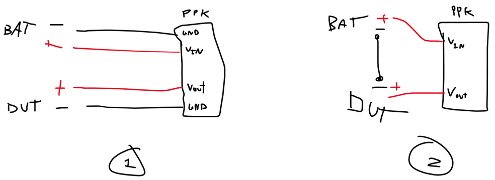
The PPK2 is connected to my laptop as the only USB device and the laptop-charger is not plugged in.


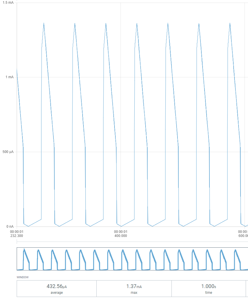
In setup (1), my deep-sleep currents measure approx. average 384 uA (10ksps) @ 10 sec:


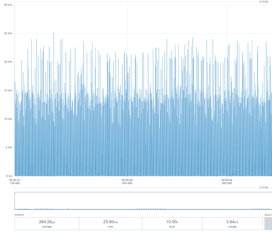
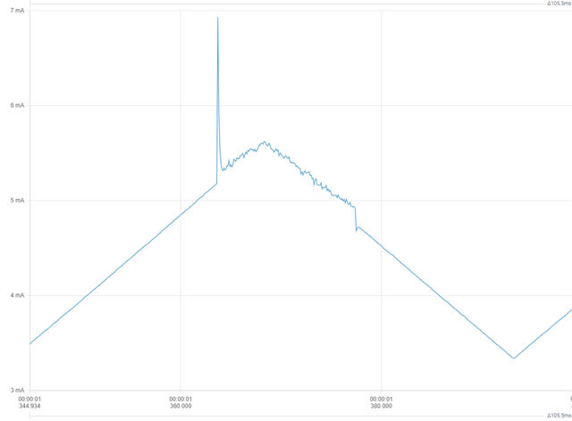
Zooming in, noticing periodic transients:


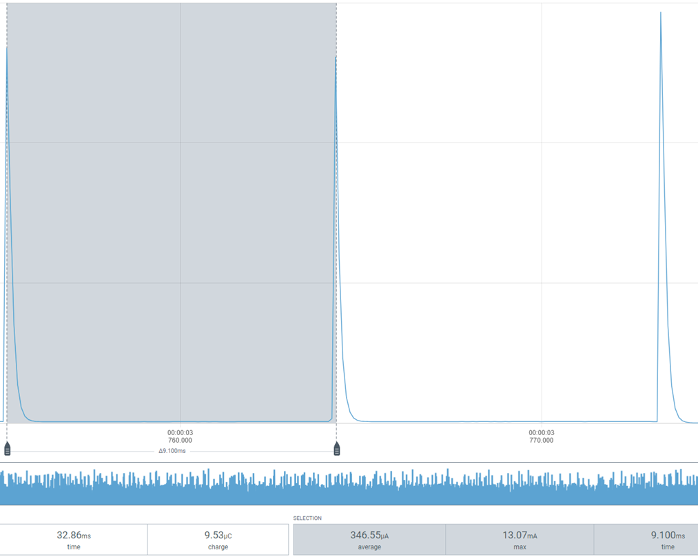
The frequency of these harmonic transients to occur changes from DUT to DUT, so might be a HW issue (ground bouncing or so) in there.

Nevertheless, if I (everything else being equal), removes the GND from the PPK2 so only the hot wire goes through the PPK2, and then connects GND from battery -> GND on DUT (setup 2), then these harmonic transients (same frequency) are much less excitated and the avg. deep-sleep current falls to ~109 uA:


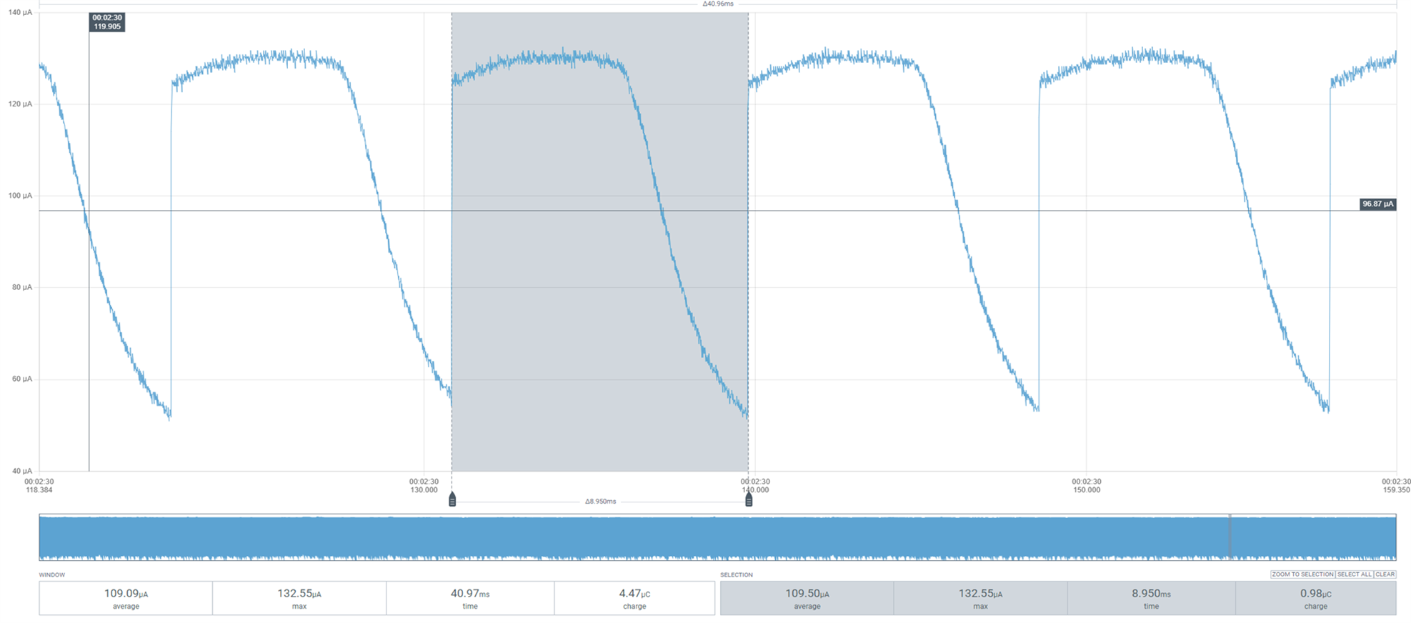
So this is a significant difference. I have also tried in source mode, but this generally yields a result of ~40 uA below configuration (2).
It seems to be a problem only connected to my DUT, or just a dynamic load. Measuring on a precision resistor yields more or less the same result.

Also, in configuration (2), I get a burden voltage of such significance that my application is not able to wake-up from deep sleep when intended to.

So I guess the primary question is; how do I assure the most precise output of my PPK2?

Can anyone me point me in the right direction? I have found some patterns of which I have a hard time concluding on, so any advice is very much welcome!

Have a nice weekend,

Br Daniel

Parents
  • Hello,

    Only setup #1 will work, you need to have ground between PPK and DUT for them to ensure they have the same ground potential:
    https://infocenter.nordicsemi.com/topic/ug_ppk2/UG/ppk/measure_current_ampere_meter.html?cp=11_9_5_2

    Normally "spikes" in measurements are caused by the internal regulator is operating in refresh mode, which means it only turn ON for short periods to charge it's decoupling capacitor. This overall reduce current consumption quite a lot.

    It's difficult to provide any more details here without actually knowing what hardware and software is doing here, without knowing more of your DUT I would say setup #1 seems to be most correct, both in terms of what they look like and actual current.

    Kenneth

  • Hi Kenneth,

    Thank you for your answer. I also noticed setup #2 wouldn't work whatsoever- so that was a bummer by me!

    DUT is an ESP32 with some peripherals connected to it, everything powered by the same Li-Ion battery. Measuring while the DUT and the peripherals are in deep-sleep.

    So the question is if the very light but dynamic load (the DUT) can cause the above mentioned behaviour with transients in the measurements, even if this is not seen with a passive load (470 ohm - 1Mohm)? 

  • Hi again,

    I thought about that too - hence my question if someone knew what threshold values are for current ranges to switch the internal shunt resistors.

    Either that or the internal regulator's operating in refresh mode. Do you know at what rate the internal cap is charged? Does this depend on DUT current consumption?

  • Using setup 1, I applied a 1Vp triangle with 1V offset and measured the current through a 470 ohm resistor to span over approximately the same current range as my DUT in deepsleep:


    Something strange happens in some of these transitions, not outputting a triangular symmetric waveform. About ~500 uA a rapid transition occurs downwards. However, peak values are as they should be (~1.28 mA).

    When going down to peak values of ~500 uA, symmetric triangle-waves are seen on the output. However, the current values are off by a factor of 10. With 250 mVpeak, 250mV offset  trangle wave over 470 ohm resistor, peak currents are measured to be 50 uA. 

    Even though the transients first discussed cannot be replicated by this, maybe this approves what have been discussed regarding switching of shunt resistors??

  • I never found out the transition switching times for the different measurement ranges, but with some loss of precision some of the switching disturbances can be defeated by using a known calibrated constant current in addition to the DUT current by using (say) a 0.1% (or even 1%) resistor in parallel with the DUT (to minimise number of current ranges used) and subtracting that constant current from the result.

    // Resistor Rc for current sense is 1k0 in parallel with one or more of 110R, 11R0, 1R0 and 0R051
    //
    //              <- +ve Supply to DUT From VOUT                               External Battery +ve To VIN
    //             +------------------------------+                             +-----------------------+
    //             |                              |                             |                       |
    //             |              +---------+     |                             |     +---------+       |
    //             |              |     GND |     | VOUT                   VIN  |     | GND -ve |       |
    //   +=========O=========+    |    +====O=====O=============================O=====O====+    |       | Battery
    //   |        Vdd (+)    |    |    |    |     #----+                        |     |    |    |       | + 3 volts
    //   |                   |    |    |    |     |    |Rc        AMPERE \      |     |    |    |     +-O-+
    //   |                   |    |    |    |     |   +++                 \     |     |    |    |     |   |
    //   |                   |    |    |    |     |   | |   +-----------O  O----#     |    |    |     |   |
    //   | Device Under Test |    |    |    |     |   | |   |                   |     |    |    |     |   |
    //   |       DUT         |    |    |    | 120k|   | |   |                   |120k |    |    |     |   |
    //   |                   |    |    |    |    +++  +++   |   \  SOURCE      +++    |    |    |     |   |
    //   |                   |    |    |    |    | |   |    |    \             | |    |    |    |     +-O-+
    //   |                   |    |    |    |    | |   +----#--O  O-- PPK LDO  | |    |    |    |       | Gnd (-)
    //   |                   |    |    |    |    | |                           | |    |    |    +-------+
    //   |                   |    |    |    |    +++                           +++    |    |
    //   |                   |    |    |    |     |                             |     |    |
    //   |                   |    |    |    |     #-- VDUT                VIN --#     |    |
    //   |                   |    |    |    |     |  Sense                Sense |     |    |
    //   |                   |    |    |    |    +++                           +++    |    |
    //   |                   |    |    |    |    | |                           | |    |    |
    //   |                   |    |    |    |    | |                           | |    |    |
    //   |                   |    |    |    |    | |                           | |    |    |
    //   |                   |    |    |    |    +++                           +++    |    |
    //   |                   |    |    |    |     | 30k                     30k |     |    |
    //   |                   |    |    |    +--#--+                             +--#--+    |
    //   |                   |    |    |       |                                   |       |
    //   |                   |    |    |     =====      <<== Common Gnd ==>>     =====     |
    //   |                   |    |    |      ===           (Common -ve)          ===      |
    //   |        Gnd (-)    |    |    |       =                                   =       |
    //   +=========O=========+    |    +===================================================+
    //             |              |     PPK-II
    //             +--------------+

  • Hello,

    Do check:
    https://docs.nordicsemi.com/bundle/ug_ppk2/page/UG/ppk/ppk_power_supply_specs.html 

    DUT voltage must be between 0.8-5V. Can you repeat the test for instance with offset 3V and 300mV amplitude?

    Edit: I believe the measurement resistors will be changed around 50uA, 500uA, 5mA and 50mA, with some hysteresis depending on whether current is increasing or decreasing.

    Kenneth

  • Hi,
    Thank you for clarification. That did the trick regarding the triangle-wave measurements. Guess also I caught the change of resistor in the 5 mA range was caught here (0.5Vpk, 2V offset):


    Will try to see if I can get good results with the good suggestion by  !

Reply Children
No Data
Related