Measure LFXO 32.768 kHz on nRF5340

Hi there

I want to measure the accuracy of the 32.768 kHz oscillator connected to a nRF5340

I have tried a lot of other devzone tickets, but most of them are too old or don't work for nRF5340.

I  also tried to use a pwm-led output with 4096Hz to measure the accuracy, but it was more than 5000 ppm inucurate (got 4117.4Hz)

Do you have a recommondation to test the LFXO accuracy with a nRF5340?

Could you provide example code?

Thank you, 

Chris

Parents
  • Hi,

    You can use the PPI trace sample. It does not include config files for the nrF5340 DK, but you can use these files:

    2117.nrf5340dk_nrf5340_cpuapp.overlay

    7888.nrf5340dk_nrf5340_cpuapp.conf

    Drop them into nrf/samples/debug/ppi_trace/boards. Then you can build for nrf5340dk_nrf5340_cpuapp. With this pin 4 will toggle with half the frequency of the LF crystall, so if you measure that with a frequency counter or simlar and multipy it by two, you have the frequency of your LF clock source (regardless if this is an external crystal or the internal LFRC).

    If you are using a custom board, rename the conf-files above to your custom board name, and that should work as well (and adjust the pin configuration if needed).

  • Hi Einar

    Thank you for your prompt replay.

    I allready tried the ppi sample earlier but I failed building it for nRF5340DK.

    Now with your files I was able to build and run it Slight smile

    I have found the 16.384kHz signal on Pin 5 of a nRF5340DK;-) 

    On pin 4 was the 50ms alarm signal.

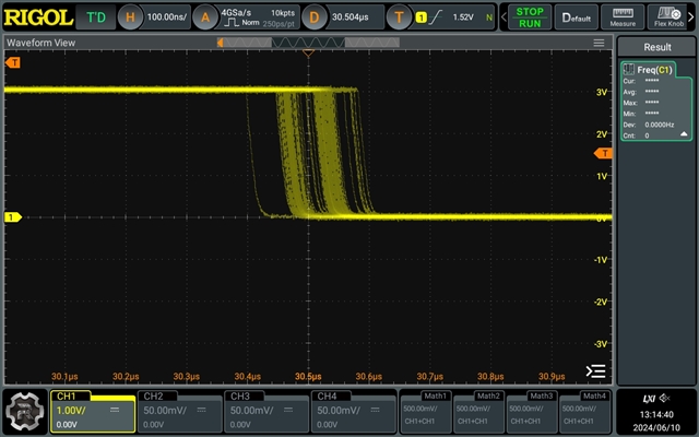
    The problem now is, that the signal has a high jitter of around 200ns:

    When I want to measure the accuracy of the LFXO I need to measure in sub-ns range. 

    10ppm would be a difference 0.3ns.

    I have tried disabling ppi_trace_pin_setup of COMPARE_EVT and STARTED_EVT but jitter stayed.

    Do you have an idea what could lower jitter?

    Thank you

Reply
  • Hi Einar

    Thank you for your prompt replay.

    I allready tried the ppi sample earlier but I failed building it for nRF5340DK.

    Now with your files I was able to build and run it Slight smile

    I have found the 16.384kHz signal on Pin 5 of a nRF5340DK;-) 

    On pin 4 was the 50ms alarm signal.

    The problem now is, that the signal has a high jitter of around 200ns:

    When I want to measure the accuracy of the LFXO I need to measure in sub-ns range. 

    10ppm would be a difference 0.3ns.

    I have tried disabling ppi_trace_pin_setup of COMPARE_EVT and STARTED_EVT but jitter stayed.

    Do you have an idea what could lower jitter?

    Thank you

Children
  • Hi,

    You can measure the average frequency of the crystal this way, but you will not be able to measure the jitter as what you are measuring here is the output of the GPIO toggeling, where you have digital logic, clock-crossing between the 32.768 kHz and the 16 MHz peripheral clock (derived from the high frequency clock source, whether that is HFINT or HFXO), etc. Maybe you will get better results by starting the HFXO (see how it is done by clock_init() in nrf/samples/peripheral/radio_test/src/main.c.

Related