QFAA-Pin mapping

Hello,
I have created a custom board with the nrf52840 QFAA and have already flashed it successfully. I do the flashing and debugging with the nrf52840dk. Now I have written code to toggle a pin. It works on the DK. On my custom board I see in debug mode that the pin is toggled. However, I cannot measure the toggling.

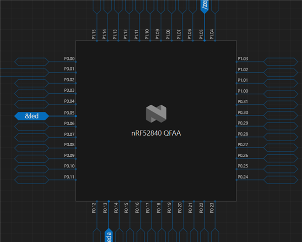
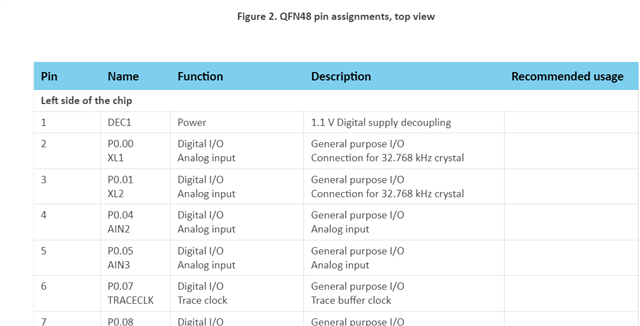
The assumption is that I am toggling the wrong pin. In the description of the VSCode extension, the naming of the pins is different than in the user manual.

Of course, it could also be that I have not configured the GPIOs correctly as peripherals. I enabeled both GPIO controllers via the VisualEditor and then added the corresponding pins via the node function.

Parents
  • Hello,

    To try to rule out any issues with the FW configuration, please try programming the attached hex file and see if that works.

    Hex file

    4682.zephyr.hex

    $ nrfjprog --program zephyr.hex --chiperase --verify -r

    Project

    pin_test.zip

    Best regards,

    Vidar

  • I flashed the test software, but the GPIO doesn't work.


    When measuring the pins, I noticed that there were 3 volts on the decoupling pins. I used the reference design from the data sheet as circuit design.

  • Which decoupling pins, on DEC4? Also, are you able to debug the application to confirm that the program reaches main()?

  • All decoupling pins have 3 volts. I can debug the program. It even goes to the main loop.
    When debugging, you can see that the pins are toggled in the register.

    I also flashed a Bluetooth example application onto the microcontroller and it worked. Only the GPIOs don't work.

  • This sounds like a hardware problem. The voltage on DEC4 should also be ~1.3V. Could you please create a new private ticket and upload your schematics along with the Gerber files for review?

  • We have found an error on the hardware side. The reference circuit diagram is poorly represented in the instructions. If lines cross, then you put a dot on the lines. Now the voltage at the decoupling pins fits. We have soldered a new microcontroller to the circuit.

    I have attached the software as a zip file. Please check if all registers are set...
    We opened the example project (Blinky) with the VS-Code Extension. Then we created a custom board (nrf52840 QFAA). We activated GPIO1, GPIO2 and GPIOTE via the DTSU viewer.
    However, the code does not toggle a pin. In the debugger you can see that the pin register is set, but no voltage can be measured.

    4718.blinky.zip

    We also need a reliable statement on which pin layout we can use for orientation. The layout from the manual or the layout from the DeviceTreeViewer from zephyr. The pin level P0.05 and so on... does not match. (Pictures in the first post)

  • We have found an error on the hardware side. The reference circuit diagram is poorly represented in the instructions. If lines cross, then you put a dot on the lines. Now the voltage at the decoupling pins fits. We have soldered a new microcontroller to the circuit.

    A dot/junction indicates a connection between intersecting wires. If wires cross without a junction, they shall not be connected.

    I have attached the software as a zip file. Please check if all registers are set...
    We opened the example project (Blinky) with the VS-Code Extension. Then we created a custom board (nrf52840 QFAA). We activated GPIO1, GPIO2 and GPIOTE via the DTSU viewer.
    However, the code does not toggle a pin. In the debugger you can see that the pin register is set, but no voltage can be measured.

    Still sounds like a HW problem.

    We also need a reliable statement on which pin layout we can use for orientation. The layout from the manual or the layout from the DeviceTreeViewer from zephyr. The pin level P0.05 and so on... does not match. (Pictures in the first post)

    The DT UI visualizes pins that can be configured in software (e.g., GPIO - Px.xx pins) and does not make any attempts to reflect the hardware layout (it does not show the package pin numbers). So, you need to refer product specification and your PCB layout.

Reply
  • We have found an error on the hardware side. The reference circuit diagram is poorly represented in the instructions. If lines cross, then you put a dot on the lines. Now the voltage at the decoupling pins fits. We have soldered a new microcontroller to the circuit.

    A dot/junction indicates a connection between intersecting wires. If wires cross without a junction, they shall not be connected.

    I have attached the software as a zip file. Please check if all registers are set...
    We opened the example project (Blinky) with the VS-Code Extension. Then we created a custom board (nrf52840 QFAA). We activated GPIO1, GPIO2 and GPIOTE via the DTSU viewer.
    However, the code does not toggle a pin. In the debugger you can see that the pin register is set, but no voltage can be measured.

    Still sounds like a HW problem.

    We also need a reliable statement on which pin layout we can use for orientation. The layout from the manual or the layout from the DeviceTreeViewer from zephyr. The pin level P0.05 and so on... does not match. (Pictures in the first post)

    The DT UI visualizes pins that can be configured in software (e.g., GPIO - Px.xx pins) and does not make any attempts to reflect the hardware layout (it does not show the package pin numbers). So, you need to refer product specification and your PCB layout.

Children
Related