Xiao BLE Sense & IMU - ZephyrOS

Hi Everyone,

I am trying to develop a simple application with the XIAO BLE Sense device, the idea is to send a BLE message with a something hits the device. To achieve this, I wanted to configure the IMU so that /*********************************/

First of all, let me summarize what I am using and what program I have uploaded to the device:

  • Hardware:
    • Xiao BLE Sense.
  • Software:
    • Visual Studio Code.
    • nRF Connect for VS Code Extension Pack (latest version).
    • nRF Connect SDK Toolchain v2.5.2
    • nRF Connect SDK v2.5.2
    • Zephyr OS.

I have used the Zephyr Example for LSM6DSL but I have modified the following piece of code:

#ifdef CONFIG_LSM6DSL_TRIGGER
        struct sensor_trigger trig;
		struct sensor_value dur;
		struct sensor_value th;
					 
		trig.type = SENSOR_TRIG_MOTION;
        trig.chan = SENSOR_CHAN_ACCEL_XYZ;

        if (sensor_trigger_set(lsm6dsl_dev, &trig, lsm6dsl_trigger_handler) != 0) {
            printk("Could not set sensor type and channel\n");
            return 0;
        }
		if (sensor_attr_set(lsm6dsl_dev,SENSOR_CHAN_ACCEL_XYZ,SENSOR_ATTR_SLOPE_TH, &val) !=0){
			printk("Could not set sensor attribute slope TH\n");
            return 0;
		}

		if (sensor_attr_set(lsm6dsl_dev,SENSOR_CHAN_ACCEL_XYZ,SENSOR_ATTR_SLOPE_DUR, &val) !=0){
			printk("Could not set sensor attribute slope DUR\n");
            return 0;
		}
    #endif
I also attach the prj.config
CONFIG_STDOUT_CONSOLE=y
CONFIG_I2C=y
CONFIG_SPI=y
CONFIG_SENSOR=y
CONFIG_LSM6DSL=y
CONFIG_LSM6DSL_ACCEL_ODR=8
CONFIG_LSM6DSL_ACCEL_FS=16
CONFIG_LSM6DSL_GYRO_FS=1000
CONFIG_LSM6DSL_GYRO_ODR=8
CONFIG_LSM6DSL_ENABLE_TEMP=y
CONFIG_LSM6DSL_TRIGGER_GLOBAL_THREAD=y
CONFIG_CBPRINTF_FP_SUPPORT=y

CONFIG_BT=y
CONFIG_LOG=y
CONFIG_BT_SMP=y
CONFIG_BT_DEBUG_LOG=y
CONFIG_BT_MAX_CONN=1
CONFIG_BT_GATT_CLIENT=y
CONFIG_BT_L2CAP_TX_MTU=247
CONFIG_BT_L2CAP_TX_BUF_COUNT=5
CONFIG_BT_PERIPHERAL=y
CONFIG_BT_DEVICE_NAME="ixi"
CONFIG_BT_DEVICE_APPEARANCE=962

CONFIG_HEAP_MEM_POOL_SIZE=2048

# This example requires more workqueue stack
CONFIG_SYSTEM_WORKQUEUE_STACK_SIZE=2048

#USB
CONFIG_USB_DEVICE_STACK=y
CONFIG_USB_DEVICE_PRODUCT="IXI Sample"
CONFIG_USB_DEVICE_PID=0x0004

CONFIG_USB_DEVICE_INITIALIZE_AT_BOOT=n
CONFIG_USB_DRIVER_LOG_LEVEL_ERR=y
CONFIG_USB_DEVICE_LOG_LEVEL_ERR=y

CONFIG_SERIAL=y
CONFIG_CONSOLE=y
CONFIG_UART_CONSOLE=y
CONFIG_UART_LINE_CTRL=y
/*********************************/
The issue that I am facing is that no events and no data from the IMU is either launched or read. The only way I could read data was when I use the 
trig.type = SENSOR_TRIG_DATA_READY.
So I am not sure what I am doing wrong or if more events have been developed in Zephyr. If so, somebody that has used other events could help me to configure it?

/*********************************/

Thanks beforehand, sorry for the inconveniences and looking forward to hearing from you.

Kind regards.

Parents
  • Hello,

    I unfortunately don't have time to look into this at the moment, but maybe you can find the following discussion useful:
    Lis3dh interrupt pins configuration 

    I suspect missing/wrong irq-gpios in devicetree node for the sensor in question.

    Kenneth

  • Hi Kenneth,

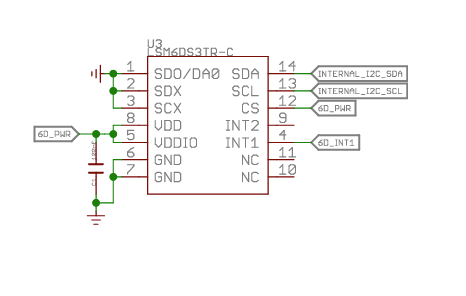
    I checked the links you shared, I am doing everything exactly the same but nothing works. After some time reviewing absolutely everything, I saw the following on the XIAO schematics:

    It seems like INT2 is not routed to anything so I guess all the motion events are not trigger because of this. The question now is,

    Is there any way we can route the "SENSOR_TRIG_DELTA or SENSOR_TRIG_THRESHOLD" events on the INT1 line?

  • I saw there is a "anym-on-int1" for then overlay on the lis3dh accel, Do you know if there is something similitar for the LSM6D?

    I paste here the DTS i am using because on my overlay there is nothing related to IMU

    / {
    	model = "Seeed XIAO BLE Sense";
    	compatible = "seeed,xiao-ble", "seeed,xiao-ble-sense";
    
    	lsm6ds3tr-c-en {
    		compatible = "regulator-fixed-sync", "regulator-fixed";
    		enable-gpios = <&gpio1 8 (NRF_GPIO_DRIVE_S0H1 | GPIO_ACTIVE_HIGH)>;
    		regulator-name = "LSM6DS3TR_C_EN";
    		regulator-boot-on;
    		startup-delay-us = <3000>;
    	};
    };
    
    &i2c0 {
    	compatible = "nordic,nrf-twim";
    	/* Cannot be used together with spi0. */
    	status = "okay";
    	pinctrl-0 = <&i2c0_default>;
    	pinctrl-1 = <&i2c0_sleep>;
    	pinctrl-names = "default", "sleep";
    	clock-frequency = <I2C_BITRATE_FAST>;
    
    	lsm6ds3tr_c: lsm6ds3tr-c@6a {
    		compatible = "st,lsm6dsl";
    		reg = <0x6a>;
    		irq-gpios = <&gpio0 11 GPIO_ACTIVE_HIGH>;
    		status = "okay";
    	};
    };
    

    Thank you!!

Reply
  • I saw there is a "anym-on-int1" for then overlay on the lis3dh accel, Do you know if there is something similitar for the LSM6D?

    I paste here the DTS i am using because on my overlay there is nothing related to IMU

    / {
    	model = "Seeed XIAO BLE Sense";
    	compatible = "seeed,xiao-ble", "seeed,xiao-ble-sense";
    
    	lsm6ds3tr-c-en {
    		compatible = "regulator-fixed-sync", "regulator-fixed";
    		enable-gpios = <&gpio1 8 (NRF_GPIO_DRIVE_S0H1 | GPIO_ACTIVE_HIGH)>;
    		regulator-name = "LSM6DS3TR_C_EN";
    		regulator-boot-on;
    		startup-delay-us = <3000>;
    	};
    };
    
    &i2c0 {
    	compatible = "nordic,nrf-twim";
    	/* Cannot be used together with spi0. */
    	status = "okay";
    	pinctrl-0 = <&i2c0_default>;
    	pinctrl-1 = <&i2c0_sleep>;
    	pinctrl-names = "default", "sleep";
    	clock-frequency = <I2C_BITRATE_FAST>;
    
    	lsm6ds3tr_c: lsm6ds3tr-c@6a {
    		compatible = "st,lsm6dsl";
    		reg = <0x6a>;
    		irq-gpios = <&gpio0 11 GPIO_ACTIVE_HIGH>;
    		status = "okay";
    	};
    };
    

    Thank you!!

Children
  • I don't know exactly which configuration options that is available on INT1 and INT2, I guess you must refer to the datasheet for the sensor in question.

    I do recommend in general to search through nRF Connect SDK for instance for 'CONFIG_LSM6DSL_TRIGGER' and check which other projects may be doing something similiar. I also recommend to have a logic analyzer available so you observe the i2c and INT1 pin, this may give valuable information what the problem may be (e.g. INT1 trigger or not).

    Kenneth

  • Well, INT1 trigger it should be working because the data ready event is triggering correctly and I2C is working correctly because I can configure and modify differet data on the IMU and the response is OK and when reading the register again it gets updated so, I dont think that should be a problem, I guess is more how to properly configure the IMU.

Related