Hi.
I am designing a 4 layer PCB (0.8mm thick) for an nRF52820 microcontroller.
My board's stack:
L1 - Signal
L2 - GND
L3 - Power
L4 - Signal
I have questions regarding the design of the ground plane under the radio transmission line.
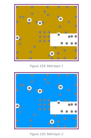
According to the datasheet recommendations, layer 2 and layer 3 should not have copper under the RF line.
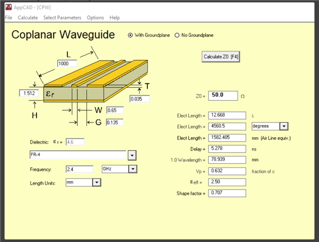
But while calculating the RF width on the JLCPCB website, you have to select the ground reference layer (in my case it is layer 2) and the result of the scoring depends a lot on that.

Do I need to fill the space under the radio transmission line on layer 2 with copper (GND polygon)? Or should I continue to follow the recommendations from the datasheet?
I hope for your help.
Thanks.