We are trying to re-layout the PCA10059 Dongle. I would like to continue to use the existing USB bootloader .hex file for updates via CDC_ACM. One thing I am confused about... Where / how does the existing USB bootloader setup the power supplies?
I believe the USB bootloader .hex file that is floating around was built using the older SDK (SDK15?)
I know that the Zephyr board config files set the BOARD_ENABLE_DCDC and BOARD_ENABLE_DCDC_HV options. But what about the bootloader - it starts first and runs even when you have nothing programmed to the board. I looked at nRF5_SDK/examples/dfu/open_bootloader/pca10059_usb/config/sdk_config.h and I see
// <i> This settings means only that components for DCDC regulator are installed and it can be enabled.

#ifndef NRFX_POWER_CONFIG_DEFAULT_DCDCEN
#define NRFX_POWER_CONFIG_DEFAULT_DCDCEN 0
#endif

// <q> NRFX_POWER_CONFIG_DEFAULT_DCDCENHV - The default configuration of High Voltage DCDC regulator

// <i> This settings means only that components for DCDC regulator are installed and it can be enabled.

#ifndef NRFX_POWER_CONFIG_DEFAULT_DCDCENHV
#define NRFX_POWER_CONFIG_DEFAULT_DCDCENHV 0
#endif
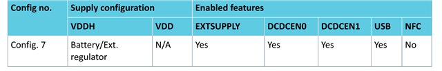
That seems to indicate DCDCEN and DCDCENHV default to disabled. Yet the PCA10059 dongle design matches Config. 7 in the datasheet:
Will the device still boot / work if DCDCEN0 and DCDCEN1 are both 0?
What about when solder bridge SB-2 is cut and SB-1 is connected? Does the device still boot / work with the same bootloader .HEX file?
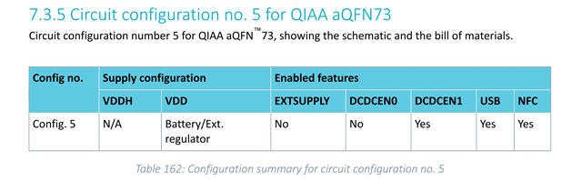
Ultimately we want to use the existing .HEX bootloader file with Config 5 in the datasheet: