2 SPI masters

Hello,

I am needing to use two separate SPI masters, but I'm running out of pins. Are all of the pins compatible with SPI or are there some I should avoid. I'm thinking of taking the pins used by the buttons, is this a good idea and how do I remove the buttons from devicetree?

Thanks in advance! 

Parents
  • Hi,


    You can use any freely available GPIO for the nRF916x:

    https://docs.nordicsemi.com/bundle/ps_nrf9161/page/pin.html


    Are you using the 9161-DK?

    If so, the board controller comes into play:

    https://docs.nordicsemi.com/bundle/ug_nrf9161_dk/page/UG/nrf91_DK/hw_description/hw_buttons_leds.html


    For the buttons, you are free to use these as you'd like, as they should be routed to the pin header by default, just remember to either delete them in DT, and/or disable any use of them in your firmware.

    Here's a way to delete the buttons section:

    /delete-node/ &{/buttons};

    Add that to the $BOARD.overlay for your specific project


    Kind regards,

    Håkon

  • Thanks for the response!

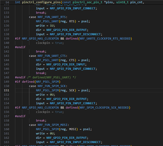
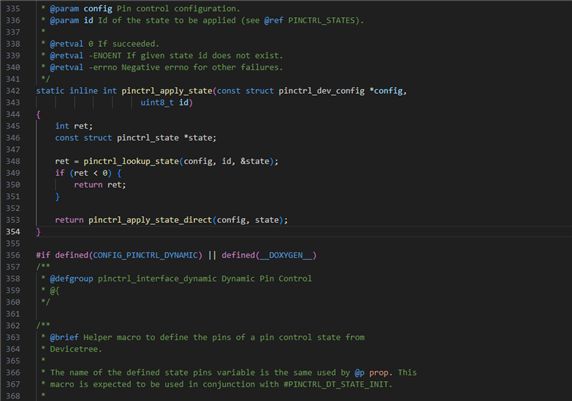
    This is what my overlay looks like. When I add the SPI1 it gives me a Zephyr Fatal Error 25. I'm not really sure what to do from here. This overlay works on a different application that I built but I don't do anything with SPI3 and the external flash whereas the asset tracker does. Any ideas on how to proceed? I used addr2line and tracked the failure to  C:/ncs/v2.6.99-cs2/zephyr/drivers/pinctrl/pinctrl_nrf.c:151

    &spi0 { status = "disabled";};
    &i2c1 { status = "disabled";};
    &uart1 { status = "disabled";};
    //&uart0 { status = "disabled";};
    //&spi3 { status = "disabled";};
    &spi2 { status = "disabled";};
    &arduino_adc { status = "disabled";};

        /   {
            /delete-node/ leds;
       
            leds0 {
                compatible = "gpio-leds";
                status = "okay";
                label = "LED0";
                led0: led_0 {
                    status = "okay";
                    gpios = <&gpio0 0 0>;
                    label = "Green LED 1";
                };
            };
       
            leds1 {
                compatible = "gpio-leds";
                status = "okay";
                label = "LED1";
                led1: led_1 {
                    gpios = <&gpio0 1 0>;
                    label = "Green LED 2";
                };
            };
       
            leds2 {
                compatible = "gpio-leds";
                status = "okay";
                label = "LED2";
                led2: led_2 {
                    gpios = <&gpio0 4 0>;
                    label = "Green LED 3";
                };
            };
       
            leds3 {
                compatible = "gpio-leds";
                status = "okay";
                label = "LED3";
                led3: led_3 {
                    gpios = <&gpio0 5 0>;
                    label = "Green LED 4";
                };
            };
       
            /* Configure partition manager to use gd25wb256 as the external flash */
            chosen {
                nordic,pm-ext-flash = &gd25wb256;
            };
       
            aliases {
                ext-flash = &gd25wb256;
            };
        };
       
        &gd25wb256 {
            status = "okay";
        };


    &i2c2 {
        mysensor: mysensor@44{ //4a
            compatible = "i2c-device";
            status = "okay";
            reg = < 0x44 >;
        };
    };

    /{
        custom_buttons {
            compatible = "gpio-keys";
            button4: button_4 {
                gpios = <&gpio0 21 (GPIO_PULL_DOWN | GPIO_ACTIVE_HIGH)>; //Pull down is very important
                label = "Custum button 4";
            };
            button5: button_5 {
                gpios = <&gpio0 17 (GPIO_PULL_DOWN | GPIO_ACTIVE_HIGH)>; //Pull down is very important
                label = "Custom button 5";
            };
            button6: button_6 {
                gpios = <&gpio0 24 (GPIO_PULL_DOWN | GPIO_ACTIVE_HIGH)>; //Pull down is very important
                label = "Custom button 6";
            };
            button7: button_7 {
                gpios = <&gpio0 25 (GPIO_PULL_DOWN | GPIO_ACTIVE_HIGH)>; //Pull down is very important
                label = "Custom button 7";
            };
            button8: button_8 {
                gpios = <&gpio0 19 (GPIO_PULL_DOWN | GPIO_ACTIVE_HIGH)>; //Pull down is very important
                label = "Custom button 8";
            };
        };

        aliases {
            sw4 = &button4;
            sw5 = &button5;
            sw6 = &button6;
            sw7 = &button7;
            sw8 = &button8;
        };
    };


    &spi1 {
        compatible = "nordic,nrf-spim";
        status = "okay";
        pinctrl-0 = <&spi1_default>;
        pinctrl-1 = <&spi1_sleep>;
        pinctrl-names = "default", "sleep";

        st7789v_st7789v_tl019fqv01: st7789v@0 {
            compatible = "sitronix,st7789v";
            spi-max-frequency = <20000000>;
            reg = <0>;
            //cmd-data-gpios = <&gpio0 15 GPIO_ACTIVE_HIGH>;    /* D9 */
            //reset-gpios = <&gpio0 14 GPIO_ACTIVE_HIGH>;   /* D8 */ //arduino_header
            width = <320>;
            height = <240>; //170
            x-offset = <0>;
            y-offset = <35>; //35
            vcom = <0x2b>;
            gctrl = <0x35>;
            vrhs = <0x0f>;
            vdvs = <0x20>;
            mdac = <0x60>;
            gamma = <0x01>;
            colmod = <0x55>;
            lcm = <0x2c>;
            porch-param = [0c 0c 00 33 33];
            cmd2en-param = [5a 69 02 01];
            pwctrl1-param = [52 a1];
            pvgam-param = [D0 00 02 07 0B 1A 31 54 40 29 12 12 12 17];
            nvgam-param = [D0 00 02 07 05 15 2D 44 44 1C 18 16 1C 1D];
            ram-param = [00 F8];
            rgb-param = [CD 08 14];
        };
    };

    / {
        gpiocustom {
            compatible = "gpio-keys";
            backlight_pin: backlight-gpio {
                gpios = <&gpio0 28 GPIO_ACTIVE_HIGH>;
                label = "Custom gpio 28";
            };
            chip_select_pin: chip_select-gpio {
                gpios = <&gpio0 16 GPIO_ACTIVE_LOW>;
                label = "Custom gpio 16";
            };
            data_cmd_pin: data_cmd-gpio {
                gpios = <&gpio0 23 GPIO_ACTIVE_LOW>; //14
                label = "Custom gpio 23";
            };
            reset_pin: reset-gpio {
                gpios = <&gpio0 22 GPIO_ACTIVE_HIGH>; //22
                label = "Custom gpio 22";
            };
        };
    };

    &pinctrl {
        spi1_default: spi1_default {
            group1 {
                    psels = <NRF_PSEL(SPIM_SCK, 0, 9)>,//13 18
                <NRF_PSEL(SPIM_MISO, 0, 18)>,//11 8
                <NRF_PSEL(SPIM_MOSI, 0, 8)>;//12 9
                    nordic,drive-mode = <NRF_DRIVE_H0H1>;
       
            };
        };

        spi1_sleep: spi1_sleep {
            group1 {
                    psels = <NRF_PSEL(SPIM_SCK, 0, 9)>,
                            <NRF_PSEL(SPIM_MOSI, 0, 8)>,
                            <NRF_PSEL(SPIM_MISO, 0, 18)>;
                    low-power-enable;
            };
        };
    };
  • Hi,


    1. Try grouping your root nodes, ie. nodes that start with a "/" :

    / {

      ...

    };


    2. You haven't defined a CSN pin for your sensor attached to SPI1?

    3. Was is the content of PC that resolved to pinctrl_nrf.c? Did the content of LR also give any indication?

    4. Could you share the compiled build/zephyr/zephyr.dts file as well as the .config file?


    Kind regards,

    Håkon

  • 1. Didn't help

    2. The chip select is defined as a gustom gpio. I'm using the adafruit graphics library to draw stuff on my screen and it wants direct control of the CS, data command, and reset pins. This implementation works just not when I chuck it into the asset tracker.

    3. Is this what you are referring to? 

    4. Yes, hopefully you can access these

    zip.zip

Reply Children
  • Thanks for sharing. It looks like uart1 is set as a secure peripheral. Try setting "CONFIG_TFM_SECURE_UART1=n" in your prj.conf file and see if the fault continues.

    mmelv said:
    Is this what you are referring to? 

    I was thinking aboutthe fault log, content of R14/LR.


    PS: you are using spi3 for gd25wb256 currently, and you're defining two cs-gpios, but there's only one sensor attached to this peripheral. Not crucial, but you'd probably want to fix it, in case you get a gpio conflict down the road.


    Kind regards,

    Håkon

  • Thanks for the response! I tried updating the config but I'm getting the same error.

    Running addr2line for R14/LR gives: C:/ncs/v2.6.99-cs2/zephyr/include/zephyr/drivers/pinctrl.h:354

  • I think the problem might be that I'm using pins that are default for buttons for my SPI MISO, MOSI, and SCK. I think the asset tracker has button handlers whereas my other implementation that the code works on doesn't. How can I remove the buttons and modify the asset tracker to work without buttons? I'm unable to do /delete-node/ buttons.

  • Hi,


    Sorry, the former config still left uart1 in a "secure" state.

    Try these:

    CONFIG_TFM_SECURE_UART=n
    CONFIG_TFM_LOG_LEVEL_SILENCE=y


    If it still does not work, could you share the updated .config?


    *edit* forgot the last question:

    mmelv said:
    I think the problem might be that I'm using pins that are default for buttons for my SPI MISO, MOSI, and SCK. I think the asset tracker has button handlers whereas my other implementation that the code works on doesn't. How can I remove the buttons and modify the asset tracker to work without buttons? I'm unable to do /delete-node/ buttons.

    You can delete the buttons by setting this in your overlay file:

    /delete-node/ &{/buttons};


    You may also have to set CONFIG_DK_LIBRARY=n


    Kind regards,

    Håkon

  • Yes, that worked! Thanks! Is there any functionality I lose by configuring:

    CONFIG_TFM_SECURE_UART=n
    CONFIG_TFM_LOG_LEVEL_SILENCE=y

Related