I was facing some buffer issues while setting up I2S, so I decided to flash and test out the i2s echo sample provided in the sample programs in the SDK. I changed the DT_NODELABEL to use i2s0 for both I2S_RX_NODE and I2S_TX_NODE. I also added debug print statements to print out the values captured by the mic as follows:
while (k_sem_take(&toggle_transfer, K_NO_WAIT) != 0) {
			void *mem_block;
			uint32_t block_size;
			int ret;

			ret = i2s_read(i2s_dev_rx, &mem_block, &block_size);
			if (ret < 0) {
				printk("Failed to read data: %d\n", ret);
				break;
			} else if(ret == 0) {
				// printk("Successfully read data (%d)...\n", block_size);
			}

			int16_t *sample_data = (int16_t *)mem_block;
			for (int i = 0; i < block_size / BYTES_PER_SAMPLE; ++i) {
				printk("Sample %d: %d\n", i, sample_data[i]);
			}

			process_block_data(mem_block, SAMPLES_PER_BLOCK);

			ret = i2s_write(i2s_dev_tx, mem_block, block_size);
			if (ret < 0) {
				printk("Failed to write data: %d\n", ret);
				break;
			} else if(ret == 0) {
				// printk("Successfully wrote data (%d)\n\n", block_size);
			}
		}
(There are no build or flash errors in this code)
This helps me make sure that the mic is being interfaced properly as it prints -1 whenever some pin connections are wrong, otherwise it will print corresponding values captured by mic. So I believe I have interfaced the microphone properly. However, I'm facing issues interfacing the speaker now as I cannot hear anything from the speaker and it seems the data is being sent properly as there are no errors.
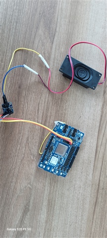
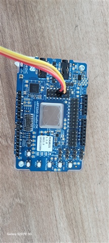
Here are the pin connections I made:
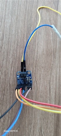
Mic: INMP441 MEMS MIC
SD: P0.15 (DOUT)
L/R: GND
WS: P0.16 (FSYNC)
SCK: P0.14 (BCLK)
Speaker: I2S MAX98357 Amp
DIN: P0.13 (DIN)
LRC: P0.16 (FSYNC)
BCLK: P0.14 (BCLK)
SD: NC
GAIN: GND
End result which Im planning to achieve: Receive audio from USB or BLE over I2S and play it to the speakers. I tried implementing a tone generator for the i2s_write function as well but that didn't work either.