This post is older than 2 years and might not be relevant anymore
More Info: Consider searching for newer posts

nRF52 NFC antenna and its equivalent inductance

Hi,

We decided to add NFC functionality to our nRF52 open source sensor beacon design, RuuviTag: http://ruuvi.com

I would like to ask your opinion about the antenna design, because Nordic hasn't published (correct me if wrong) any white papers or design guidelines about the NFC antennas.

Our NFC design files can be found from here: github.com/.../nfc-antenna

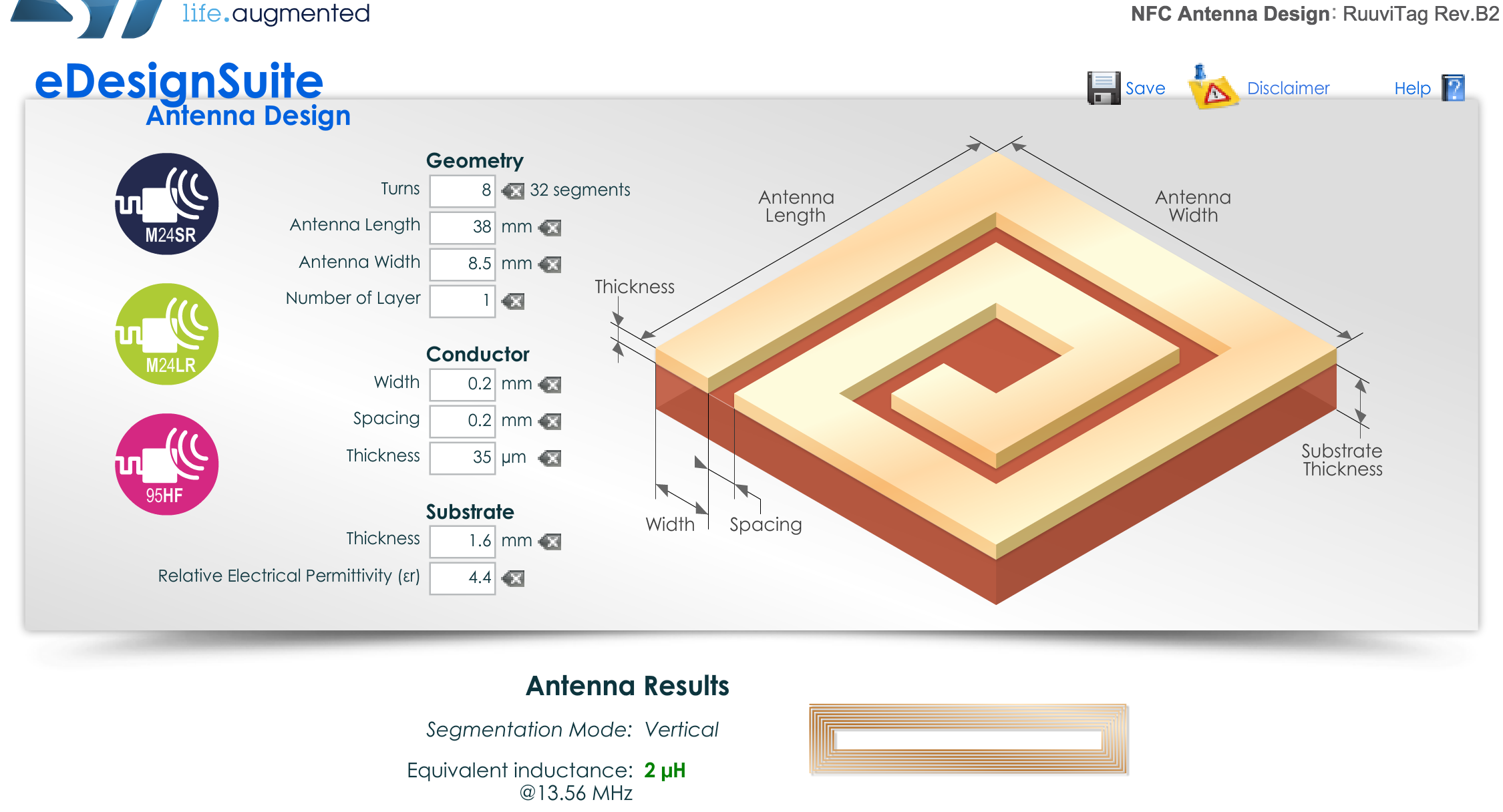
First I used STM's eDesignSuite to match the equivalent inductance to 2uH:

image description

After that bended the antenna to fit our design:

image description

Would it work? It sure needs tuning capacitors in place, but AFAIK, we need to make some measurements to find the correct values...

Parents
  • Hi,

    With the NFC antenna there is always a bit of a compromise. More turns mean a higher mutual inductance (better coupling) but you will end up with a lower Q factor. As mentioned by Anders as long as you can tune it to 13.56MHz it should be OK (given that the antenna is very small you will want to tune to exactly 13.56MHz).

    However, the very small antenna will lead to a extreme low coupling with any reader and that in turn will mean a very bad read range (worst case even no read at all depending on the size of the reader antenna).

    I did such designs before (RFID / BLE combo boards) and the general construction which seemed best for me was:

    NFC/RFID antenna on the outskirt of the PCB (maximize the size for good performance). As the BLE antenna is inside the NFC antenna I tend to use a slot antenna. I found that a monopole has huge performance issues (is diffciult to get tuned well) as there is too much intercation with the NFC coil running on the outside.

    Such a change may mean a lot of re-layouting for you, so I am not sure you really want to go for it.

    Depending on the reader you want your beacon to work with the current antenna may be good enough to read at least in corner positions (I never measured the NFC RF properties of the nRF52 so I do not know paramaters like load modulation amplitude to provide a better estimate).

    I hope this helps anyway!

Reply
  • Hi,

    With the NFC antenna there is always a bit of a compromise. More turns mean a higher mutual inductance (better coupling) but you will end up with a lower Q factor. As mentioned by Anders as long as you can tune it to 13.56MHz it should be OK (given that the antenna is very small you will want to tune to exactly 13.56MHz).

    However, the very small antenna will lead to a extreme low coupling with any reader and that in turn will mean a very bad read range (worst case even no read at all depending on the size of the reader antenna).

    I did such designs before (RFID / BLE combo boards) and the general construction which seemed best for me was:

    NFC/RFID antenna on the outskirt of the PCB (maximize the size for good performance). As the BLE antenna is inside the NFC antenna I tend to use a slot antenna. I found that a monopole has huge performance issues (is diffciult to get tuned well) as there is too much intercation with the NFC coil running on the outside.

    Such a change may mean a lot of re-layouting for you, so I am not sure you really want to go for it.

    Depending on the reader you want your beacon to work with the current antenna may be good enough to read at least in corner positions (I never measured the NFC RF properties of the nRF52 so I do not know paramaters like load modulation amplitude to provide a better estimate).

    I hope this helps anyway!

Children
Related