Hello,
I've just finished my first layout for nRF51422. Anybody out there who could have a look at my design file and tell me if it is going to work?
Relevant details:
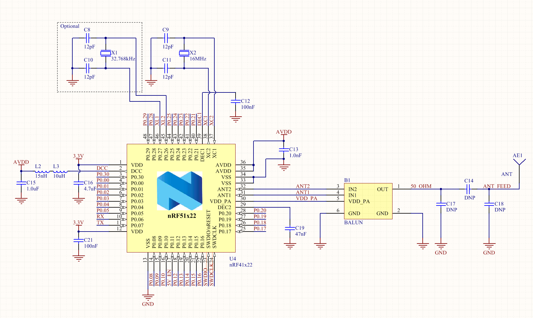
- nRF51422 in QFN packaging, configured to use internal buck regulator for the radio (hence L2, L3, C15)
- Johnason Tech 2450BM14E0003 balun (according to this doc, is the correct one to use with QFN)
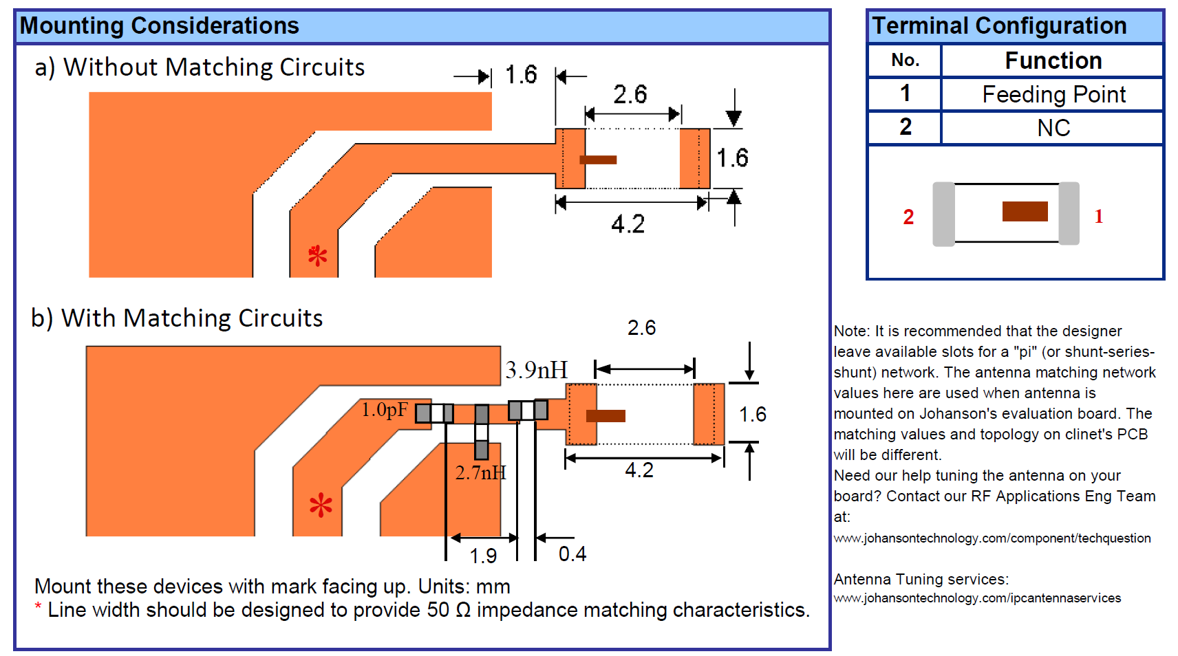
- Johanson Tech 2450AT18A100 chip antenna (I got scared of the idea of shaving a printed one)
- Pi network for matching the chip antenna to the 50ohm output of the balun
- Slice in ground plane under feedline and matching stuff
- 1.6mm feed between RF ground plane and actual port of chip antenna (like in the antenna datasheet)
- Feedline is 45mil (~1.1mm)
- Standard issue 62mil FR4 from a boardhouse in China, dielectric unknown
Questions:
- Is it a potential problem that the 16MHz crystal is close to the ground plane for the RF part? It's fairly far away from the actual feedline, but still.
- I did a bunch of reading about how to size the feedline, and found many different answers. But they are all pretty ridiculously large for 62mil FR4. In the Nordic reference designs, the output lines are just the size of the pads they are feeding. So I'm feeling confused about feedline sizing out of the balun, through the pi network, and to the chip antenna.
- How much am I REALLY going to have to tune the matching network? I only need a range of 10 meters or so.
- Right now, I am using the balun and chip antenna because this is one of my first RF designs. Any chance that it would Just Work(TM) if I copy the matching network and antenna from the nRF51 Dongle (as suggested here)? It would be nice to shave some $$ off of the cost of the project.
- Anything else I am neglecting to consider?
Thank you!
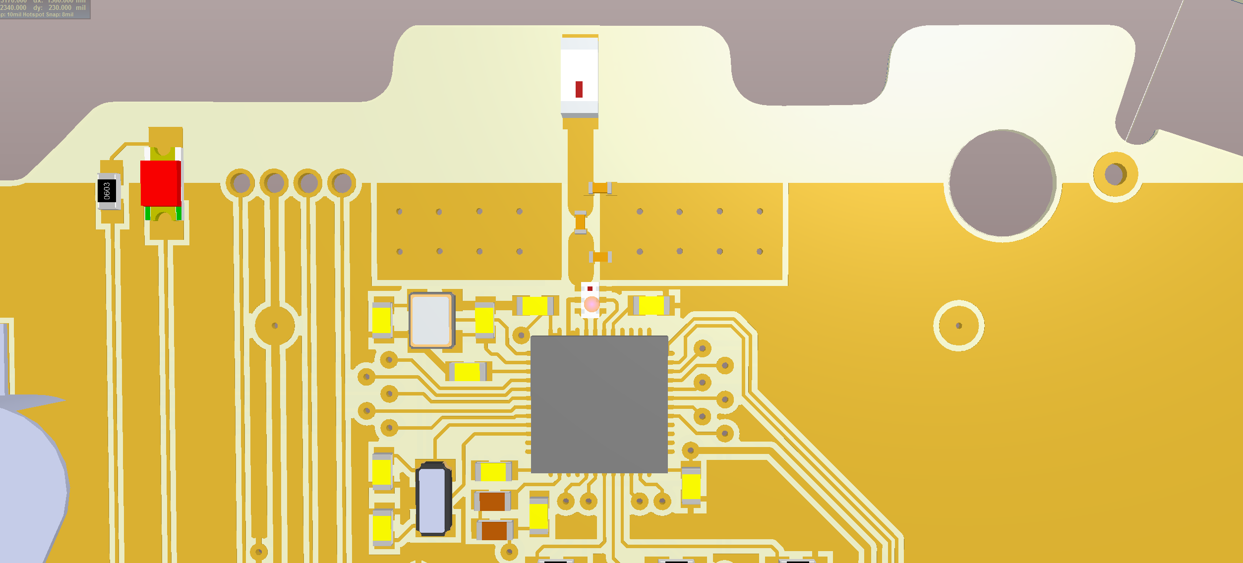
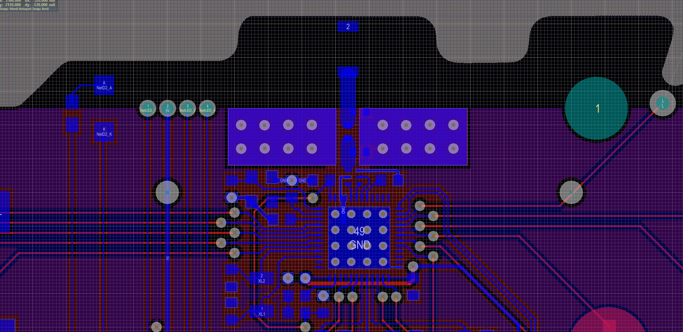
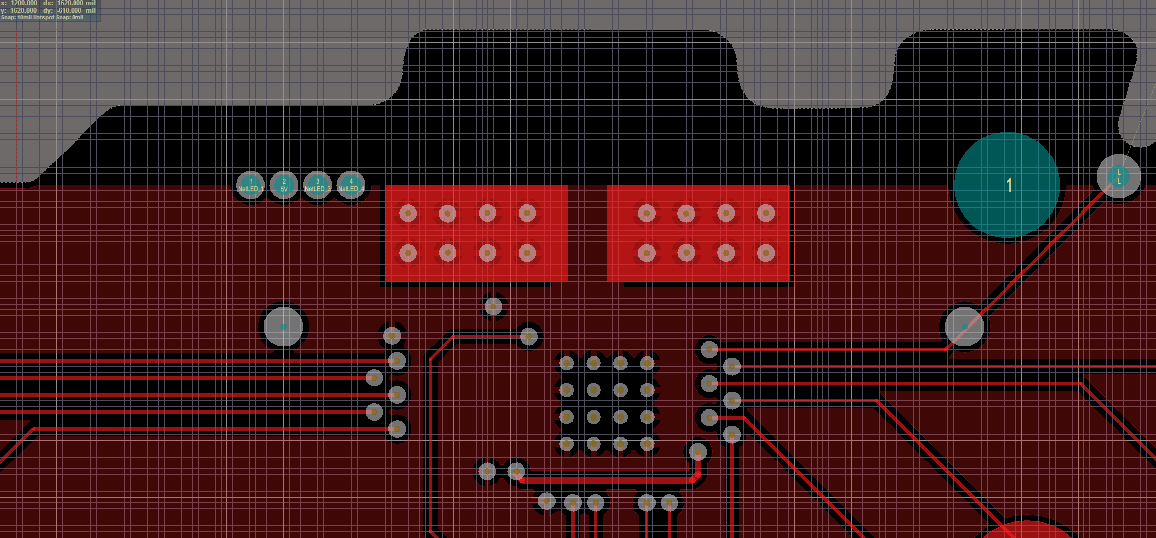
edit: pictures